Measurements Required for DIY 3D Printed Hand Prosthetics

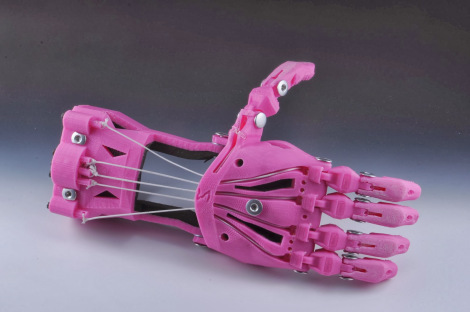
Cyborg Hand v7.0

Cyborg Hand v7.0

I’ve recently embarked upon a quest to create a parametric version of the e-NABLE prosthetic designs.  I’ve chosen the “Cyborg Beast” as it came highly recommended and I had the good fortune to meet one the main designers.

I have a habit of diving headfirst12 into a project I know absolutely nothing about and learning just enough to be dangerous as I go.3 Even if the results aren’t what would be called “successful” under normal circumstances, they do tend to be entertaining.

I generally get started by asking a ridiculous amount of questions.4 I have some guesses, but no concrete answers to the below.  If you know, I’d greatly appreciate any comments or replies.  Here’s a bunch to get us started:

  1. What are the minimum required measurements to create a suitable prosthetic, such as the Cyborg Beast?
    1. Knowing the minimum required measurements would allow a designer to better create a parametric design.
    2. The Cyborg Beast instructions refer the builder back to the measurement instructions for the Snap Together Robohand by Michael Curry aka Skimbal. These instructions indicate that all you need is the measurement of the width of the hand, where the hand is held flat with the fingers together, at the widest point on the knuckles.  Based upon the ratio between the subject’s knuckles and the stock Robohand knuckle block, all of the parts for the model are then scaled up or down.
    3. The ease of reference, the entire set of instructions for the Snap Together Robohand are as follows:
      1. Measure the length of the individual’s knuckles across the back of the hand

      2. from the index to pinky finger. (Example: 85mm)
      3. Add 5mm to your measurement to account for the thickness of the gauntlet.

        (Example: if the individual’s hand measures 85mm knuckle-to-knuckle, add 

        5mm for a total length of 90 mm).

      4. The knuckle block in the files you downloaded is 65mm. Divide your result by 

        65. (Example: 90/65 = 1.38).

      5. Multiply the answer times 100 to get a percentage. 

        (Example: 1.38 x100 = 138%).

      6. Scale all the parts of Robohand by this percentage before printing. This can b

        e done using the ‘Scale’ tool in Makerware.

    4. Are there any other measurements, besides the width of the hand at the knuckles, required to create a suitable custom prosthetic?
  2. How do these measurements inform a customized prosthetic design?
    1. Scaling all parts equally makes sense for a “snap together” design where all the parts, including the fasteners, are sized together.  When one is using stock parts (such as screws, elastic cord, and nylon cord)), this approach can end up requiring the builder to do a lot of post-printing work widening holes or trying to find wider screws.
    2. Other than scaling all parts equally, based upon knuckle measurements, is there any other modifications to the printable design required in order to create a useful prosthetic?
  3. How accurate do these measurements need to be in order to create a suitable prosthetic?
    1. Do the measurements need to be down to the micron?  Is within about 1mm or so good enough?
  4. For each required measurement, is it better to round it up or down?
    1. If the only required measurement is the width of the knuckles at the widest point, I suspect that it is probably better to round this figure up, rather than down.  I believe it would be much easier to add a little extra padding or tighten the velcro strapping a bit more.
  5. What are the important structural features of the Cyborg Beast?  As in, what parts, dimensions, and part relationships are absolutely critical to its proper function and fit?
    1. I’m very very weak in this area.  I just don’t know which parts are “load bearing” and are so critical to the function of the device that I should make special efforts to replicate them in my design.  Any suggestions here are greatly appreciated.
    2. I suspect that the critical functional features include part thickness (especially where separate parts meet – for strength and durability), the height and length of the “outcropping” on the back of the wrist which appears to provide the mechanical advantage which causes the fingers to constrict, and the tightening block on the gauntlet.
  6. What are the important design features of the Cyborg Beast?  As in, what parts, dimensions, and part relationships are critical to the suitability of this model over others?
    1. Again, I’m incredibly weak in this area.  I suspect that the overall organic shape to the model is one of its most stand-out features.  However, I would invite more informed comments and observations.
  7. What parts of the Cyborg Beast are the most improved?
  8. What parts of the Cyborg Beast are most in need of improvement?
Default Series Title
  1. Almost willy-nilly, if you will. []
  2. You will, won’t you? []
  3. I imagine this is what it is like to learn to fly. []
  4. If you don’t believe me, feel free to peruse this site where you fill find literally thousands of words on the smallest design variations on the smallest parts for a drawing robot []

Possibly Parametric Prosthetics

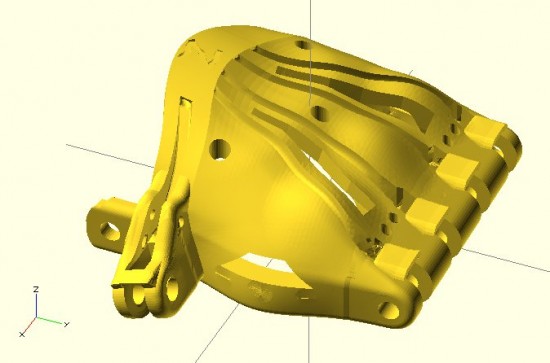
Cyborg Beast v7.0

Cyborg Beast v7.0

This last Friday I journeyed to the Autodesk offices at Pier 9 in San Francisco to attend a meeting for e-NABLE, a group devoted to developing, making, and distributing DIY prosthetics.  I have to admit that my own personal interests weren’t necessarily aligned with that of the entire group.  I’m sure those there would forgive my trespasses, but I am far more interested in making the prosthetics and in making it easier for others to make similar prosthetics than I am in the actual mechanics of building an organization that does these same things.

I came away from the meeting having met some amazing people doing amazing things, and with considerably more knowledge than that with which I arrived.1 Just as with the RepRap project, the daunting part of getting started in this field is wondering where the heck to get started.  There are so many different models being developed and so much information, that I just was not sure how to go about actually making such a prosthetic.

As frequent readers of this blog2 know, I like to treat this site as something of an online open notebook where I share my notes, thoughts, and ideas.  Thus, here are the most helpful things I learned as a result of this meeting:

  1. Where to Get Started
    1. Jonathan Schull, an associate professor at the Rochester Institute of Technology, was patient and kind enough to provide me with some pointers on where to get started with producing 3D printed prosthetics.  Jon suggested the Talon Hand for strength, the Cyborg Beast for general use, and the ODY Hand for young children.  The Cyborg Beast instructions refer one to the measurement instructions for the Snap Together Robohand by Michael Curry aka Skimbal.  The process, as far as I understand it, involves measuring the subject’s hand and scaling all of the parts up or down accordingly.
  2. Taking Measurements.
    1. Professor Jorge Zuniga, of Creighton University in Nebraska, is currently using a system for taking measurements that involves taking three photographs of a person’s upper extremities in different positions.  The photographs are taken with a ruler in the image, so that the measurements may be extrapolated.  In talking with Professor Zuniga, I learned that while this is a good way to get a lot of information very quickly (take three quick photographs), it can be labor intensive and time consuming to actually extrapolate the various measurements.
    2. It occurred to me that this sort of problem has actually been solved reasonably well.  Marty McGuire 3 and Amy Hurst created a system for using pictures of hands with standardized objects to extrapolate hand measurements for the creation of custom 3D printed objects.  In the case of their NickelForScale project, they used a photography setup and OpenCV to create custom rings.  While OpenCV isn’t exactly the easiest thing to dive into, one it was figured out could reap huge time savings in gathering the measurements necessary to create custom prosthetics.
  3. Customizing Printable Prosthetics
    1. The multi-step process of taking pictures of a subject’s hands, extrapolating the necessary measurements, calculating the scaling factor, scaling the files up or down, then printing seems fairly involved to me.  While none of these individual steps are actually that complex, it is entirely possible to automate much of this and lower the barrier to getting people involved.
    2. One interesting problem that is created by scaling parts is that certain parts of a design probably shouldn’t be scaled – such as the channels for routing cables or holes for the Chicago screws.4 This inadvertent scaling problem can be completely solved by use of a parametric modelling program, such as (my personal favorite) OpenSCAD.  The “trick” is to scale the model and distribute the various channels for routing cables and screw holes to the appropriate positions to match the new scale – without scaling the diameter of these voids.
    3. One of the really great things about the Cyborg Beast prosthetic model is its extremely realistic and organic appearance.  While OpenSCAD is definitely well suited to creating functional models, it is not as obvious how to create organic seeming solids.  Fortunately, MakerBot’s handsomest and most modest blogger5 posted a very comprehensive tutorial on creating organic solids with OpenSCAD.
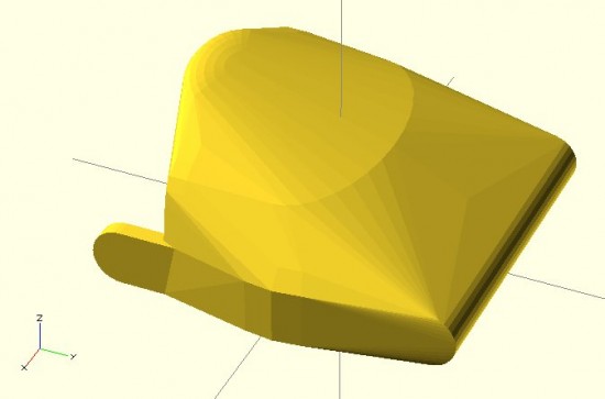
    4. Last night I got started on creating a parametric Cyborg Beast model.  While I’m not going for a completely faithful translation of the Cyborg Beast into a parametric model, I’m shooting for a reasonable facsimile of the most important structural and cosmetic features of the Cyborg Beast.  Below is a screenshot of this work in progress.  There’s no thumb joint in this model yet, but it’s coming along.
Cyborg Beast OpenSCAD prototype

Cyborg Beast OpenSCAD prototype

Obviously, there’s more work to do embellishing this model, including adding the thumb joint, hollowing out the underside, adding the knuckle stops for the fingers, and the voids for routing the cables and screws.  However, it’s not that bad for a little bit of quick OpenSCAD hackery.  After that’s done, the various other parts would need to be replicated in OpenSCAD as well.

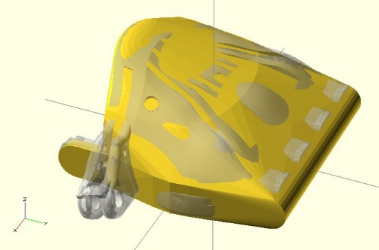
Cyborg Beast OpenSCAD prototype with original Cyborg Beast overlaid

Cyborg Beast OpenSCAD prototype with original Cyborg Beast overlaid

Default Series Title
  1. That is to say, a lot more than zero! []
  2. Both of you! []
  3. Don’t let the abandoned website fool you – he’s a busy guy moving fast making awesome things []
  4. Head’s up – Chicago screws have a slightly more common and slightly less SFW name []
  5. AHEM *cough* []