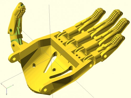
An illustrative hand
My overall designs for a printable parametric hand are still far from done. And, yet, I’ve come a long long way since jumping headfirst into the realm of open source prosthetics a little more than 30 days ago.12
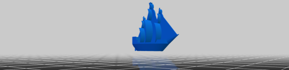
Forgive the digression, dear reader, before I return you to considerations of prosthetics. After visiting the Asian Art Museum today with the family, I am feeling particularly inspired to discuss dualities.3 I find I am an often-inspired person. This is a very charitable way to describe myself by what would otherwise colloquially and clinically be considered ADHD. When I am inspired by a new topic, I tend to jump right into it – reading voraciously and trying to learn as much about it as I can. When this happens, I also tend to set aside whatever thing I was most recently working on. This means that recently I’ve done little work on drawing robots (big and small) and a multitude of other small projects that would otherwise be just amazing. However, such inspirations/distractions are not only external to a project – but can also be very much internal to a project. Consider, for instance, feature creep – the adding of ever more features to a project, usually at a faster rate than which features are resolved and refined. In order to combat this aspect of my nature, the wanting to add more and better features, I have developed a coping mechanism. To prevent myself from falling down the rabbit hole of features and improvements, I jot them down someplace – either in a blog post4 , in an email to myself, or in a notebook.5 I find that once I’ve externalized and memorialized an idea, I can continue working on a project unfettered and undistracted these other ideas.
To this end, and in the spirit of open source ideals, I will jot down some ideas while I have them:
- How large and how small are prosthetic designs typically scaled?
- I wanted to have a range of sizes for which my designs were optimized. My guess would be no smaller than 85% and not much more than 160% of the size of the existing Cyborg Beast. Jorge Zuniga was, again, patient enough to discuss this with me. His estimate of a range would be between about 105 – 150%.
- What is the diameter of the Chicago Screws typically used in the creation of a Cyborg Beast?
- From the retailer’s website, it appears the “barrel” diameter is 0.2 inches, or 5.08mm. I’ll need to make some adjustments to holes for the Chicago Screws in the designs.
- How important is hyperextension of these fingers?
- The designs of the Cyborg Beast include fingers that can bend “backwards” very slightly. Each finger joint includes a “stop” at the back of the joint. While certainly useful, I question their necessity. I previously designed a connection system for printable snap-fit parts ((For use in an equally noble project)) that connect very tightly and/or bend with a user specified degree of movement. The point with me mentioning these parts is that the “stop” used at the back of each knuckle and joint in the Cyborg Beast may not be necessary at all.
- How necessary are metal Chicago Screws to strength and durability of the hand and fingers?
- Before you laugh, consider this question – what is the weakest point of any given finger which uses a metal Chicago Screw when having to deal with lateral forces? I would postulate the weakest points would be those thin plastic parts surrounding the Chicago Screws themselves. Thus, even though the hand incorporates metal pins, I have to wonder just how much strength they are providing to the overall device. It would be easy to conceive of a plastic prosthetic hand that was so small that there wasn’t a lot of plastic around each metal screw6. In such a case, the weakest points would be plastic surrounding the metal parts. Extending this conjecture, of what use are metal fasteners to a design that is primarily plastic? The best guess I can offer is that they allow reliable and smooth operation.
- Work on proportional fingers
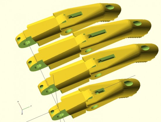
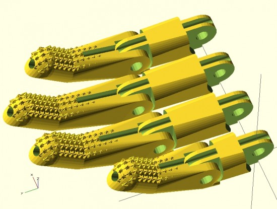
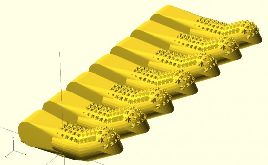
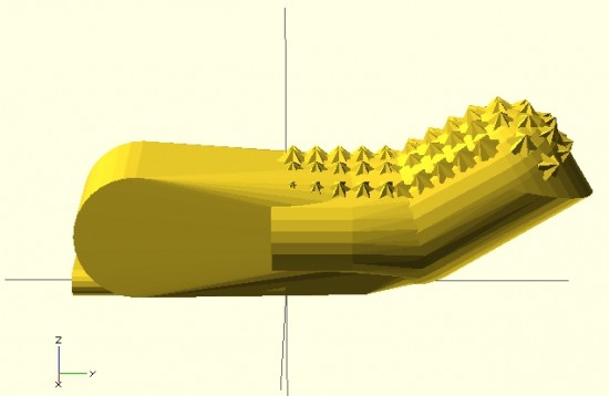
- In designing the fingers, I worked to be able to make them customizable in several different ways. The user may specify whether the fingers have the “star grip” pads, whether the finger should be slightly shorter or longer, and scale the finger up or down – without distortion to the hardware and cord channels.
- I need to add at least three additional options to these parametric designs. The designs should include the option to add “mouse ears” and easily removable support structures. Additionally, the design should also allow the user to change the diameter of the finger. I did implement this, somewhat, in part of the design. Without implementation throughout the entire design, these partial attempts aren’t helpful.
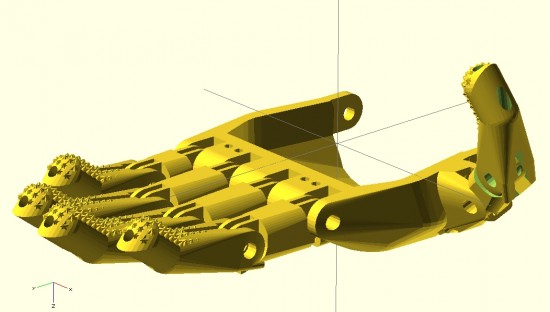
- In creating the fingers shown above, I adjusted their lengths to conform to the measurements of my own hand.7 Next time, I think I would also measure finger diameters.
- I think I should create a way to prevent finger parts from being mixed up accidentally while printing. A possible solution is to include “mouse ears” with each finger – but embed an identifying mark in each mouse ear to label the parts.
- Ideas on making a better parametric palm
- The palm should be redesigned so that the fingers, at the appropriate lengths, would fit into it. I designed the fingers quite a while since working on the palm. I haven’t had a chance to ensure the parts would mesh well without adjustment to the scale.
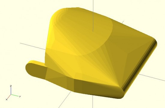
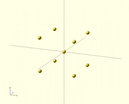
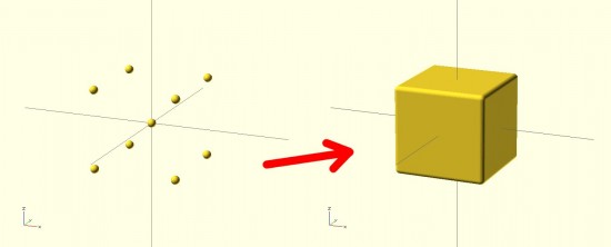
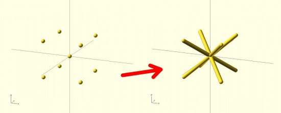
- On an entirely different note, I have an idea to redesign the entire palm. By carefully placing deformed spheres, I was able to design a palm. Using a similar process, I subtracted out a void for the user’s hand. The result is a palm with an uneven thickness throughout. Uniform thickness isn’t necessarily an interesting or useful goal. That said, it could lead to a reduction in unnecessary plastic. If I were to redesign the palm, I could design the internal area first8 – and then use the “Minkowski” function to create a uniformly thick shell around the internal form. The bottom would have to be sliced off and the original internal area would need to be subtracted from it.
- Ideas on making a more realistic hand
- My designs so far are based primarily on the Cyborg Beast, with some minor changes. The “Flexy-Hand” appears to be very organic and realistic. It also features flexible printed connections between each finger segment. Additionally, each finger is comprised of three segments – rather than two like the Cyborg Beast. Interestingly, since the flexible connections between segments allows the hand to return to an “open” position, the hand only requires five tension cords – rather than five tension cords and five elastic cords. The fingers appear to not have any “stops” behind each joint. I have to wonder how having three segments to each finger impacts the function. Does it allow the hand to better grip things? Does it make the hand less sturdy?
- Masculine/Feminine hands
- One well-intentioned comment to my latest designs is that they are “pretty.”9 While I accept the compliment with the spirit in which it was given, it immediately made me wonder – is the hand I designed “feminine?” Then it occurred to me that with more design effort, I could make “feminine” and “masculine” version of these hands. I think the primary differences would be two-fold – thinner fingers and a less “hefty” palm for a more feminine version and a thicker and perhaps more “blocky” palm for a more masculine hand.
- New developments
- There have been a number of interesting and new developments and experiments of late.10 In no particular order, these ideas are:
- Discussions with a 7-year-old
- A few days ago my daughter and I were jotting down some ideas in my sketchbook. As we did so, she saw some of the notes from the e-NABLE meeting on 3/21/2014 – including several sketches. We discussed the problem – affordable, customized, and comfortable prosthetics. We talked about amniotic band syndrome, how fibrous amniotic bands affect fetuses, and the different ways in which these bands can cause11 deformities to single fingers, whole hands, and a range of changes in between. I explained how Mr. Jose Delgado Jr. had a $42,000.00 myoelectric prosthetic, the problems he has with that prosthetic, how and why he prefers his $50.00 printed replacement, and how for the price of his one prosthetic people could make 840 more prosthetics.12 She asked, “Why can’t someone use a stump to operate a hand?” I replied that this was exactly how these prosthetics worked – and I drew a few simplified sketches of the Cyborg Beast. Her next question was, “Why can’t it move side to side?” I said that Mr. David Ogreman had designed such a prosthetic.
- My first concrete step was going to an e-NABLE meeting in San Francisco on 3/21/2014. [↩]
- The above picture is slightly misleading. I haven’t confirmed that the fingers I’ve designed will properly fit into the palm that I’ve designed – or that the thumb would work at all. Thus, the picture is partially a parlor trick and partially an indication of where I hope to take this design. [↩]
- Many of the gods and goddesses in Eastern religions embody dual natures – creation/destruction, life/death, etc [↩]
- In one of my several different blogs. Besides, what could be more ADHD than having 3+ blogs?!? [↩]
- You may not find this as amusing as I do – but I probably have about four different sketch/notebooks. [↩]
- Say, only 1mm [↩]
- From pinky finger to thumb, the non-scientific measurements from knuckle to finger/thumb tip were 77mm, 102mm, 106mm, 92mm, and 72mm [↩]
- Using the deformed spheres and hull trick [↩]
- Thanks Erik! [↩]
- I don’t even know why I’m saying “of late” when I’ve really only been involved a little over 30 days. I guess becuase these developments are new to me? [↩]
- Please forgive my lack of a more politically correct term. If you’ve got a better or more sensitive phrase, please let me know as I will gladly adopt it [↩]
- She wanted to know if he could get a refund! [↩]