Considering the design elements of a DIY light saber

I like to think about projects in discrete parts, trying to solve one part, then moving onto another section.  In the case of this DIY lightsaber build, I’ve been burning some brain cells thinking about this project.  Just by looking at the publicly available images of the TwistSaber, what can I infer about it’s construction?
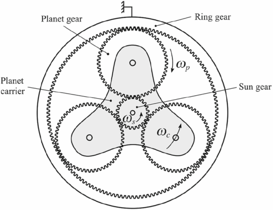
Planetary Gears

TwistSaber Gears

I would guesstimate the gears are probably about 8 mm in height.  When I want to make a very sturdy part, I’ll use a 3 mm thickness.  However, these gears look extra chonky, so let’s go crazy.  Making further, and more in depth, guesses…  Let’s see what happens when we toss the above image into Inkscape and try to lay some star shaped polygons on it.

This slideshow requires JavaScript.

I would estimate the ring gear has 58 teeth, the planetary gears appear to have 20 teeth, and the sun gear to have 10 teeth.  When you’re dealing with printing with tight tolerances and thick (0.4 mm) extrusions, you can’t make the teeth too small, but you need enough teeth so permit smooth operation.  In any case, we can count on some sweet OpenSCAD gear library magic to help us design these planetary gears.

Screw Threads

Since we’re already talking about the planetary gears, let’s think about the spiral core rotations and screw thread.  If the 58 tooth ring gear goes through a half rotation, it will rotate the 20 tooth planetary gears by 26 teeth, causing just over 2 rotations of the 10 tooth central sun gear.  The math should math like this:

  • ((ringTeeth / planetaryTeeth)) * (0.5 rotations) * (planetaryTeeth / sunTeeth) =
  • (58 / 20) * 0.5 * (20 / 10) =
  • (58 / 20) * 0.5 * (20 / 10) =
  • 58 * 0.5  / 10 =
  • 29 / 10 = 2.9

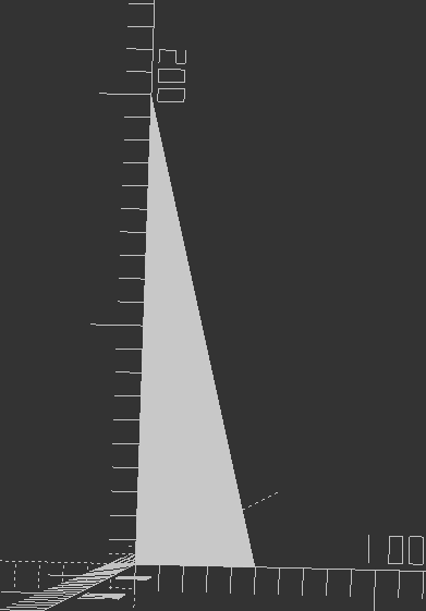
This tells us the half turn of the hilt should cause nearly 3 turns of the central spiral core.  If we had a zero degree spiral around the central core, the screw thread would not be a spiral but rather a straight vertical line.  If we had an absolutely crazy spiral, like a million degrees of turn, the screw thread would be nearly horizontal.  We’re going to need a slope for the screw thread that causes 2.9 revolutions over 200 mm.

Screw Core

The three central screw segments have some interesting design elements.

This slideshow requires JavaScript.

By tracing the image of the screw threads, in alternating yellow and red, we can see the path of the screw threads on the camera facing side of the tube.  However, by duplicating these tracing and flipping them along a horizontal axis, we can see this means there’s just two screw threads.  In an earlier post I had wondered at the optimal number of screw threads.  You want sufficient separate threads to work to actuate the core evenly, but not so many that they introduce unnecessary friction.

We already know from various videos and GIFs the screw core is attached to the hilt at the thinnest of the three segments.  It’s interesting then that the two larger tubes have flared ends with rounded notches on one side.  Although I don’t have a photo or still frame to show this, I suspect these are meant to lock against the base of the blades.  My working theory is you insert the core into the nested blade segments, and then pull them back so they click into the base of the blades.

Here’s my thinking…  let’s assume the spiral core pieces do not connect to the blades segments at all – except at the very bottom and very top.  When you rotate the spiral core center, the other two core segments could extend – but might do so unevenly based upon how much friction there might be between any two adjacent parts.  If the spiral core pieces do connect to the blade segments, then each of the three blade segments should actuate at the same rate (rather than whichever one has the least friction).

I need to give this more thought – I have an idea, which if correct might be a simpler way to design this mechanism for 3D printing.  (It would be probably impossible for injection molding though…
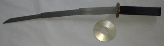
Blade Segments

The blade segments are interesting in their own right.  There’s no clear picture of how many rails exist within these blade parts.  However, we might be able to extrapolate this from the portions we can see.  In the second of these two screen shots, you can see two and a half sets of rail alignment nubs.  If there is an equal number on the reverse, then perhaps there are five alignment rails inside each blade?

This slideshow requires JavaScript.

One nice thing about OpenSCAD is the use of parameters.  There’s no reason I couldn’t design a similar device, but specify the blade segments should only be 20 mm tall, and then print out an incredibly stubby light saber.  If the mechanism work, then I could just adjust the blade segment height from 20 mm to 250 mm and try printing it again.

DIY Lightsaber Build
  1. TwistSabers
  2. DIY Lightsaber Thoughts
  3. Wait, haven’t I worked on this before?!
  4. Considering the design elements of a DIY light saber
  5. More Musings on Lightsabers, Mechanical Components
  6. Slow Progress…
  7. Capstan Drives as alternatives to Planetary Gears?

Wait, haven’t I worked on this before?!

Years ago one of my kids had a pirate themed birthday party.  I interpreted it as a “space cowboy pirate” and went with a slightly Firefly-meets-Treasure Planet theme.  My outfit included a 3D printed telescoping monocle / eyepatch and a katana that collapsed into the handle.  I was going to install some Neopixels in the eyepatch / monacle, but ended up just putting more LED’s into other projects.  Anyhow, here’s a slightly blurry picture from May of 2016 featuring a print of this steampunk telescoping monocle / eyepatch, a Chromebook, and my MakerBot Replicator 1 Dual extruder in the background.

Telescoping steampunk monocle eyepatch, fit for a space pirate

This lead me to trying to track down the files for the monocle which had been originally sized to house a Circuit Playground and a battery, then the telescoping components as well.

This slideshow requires JavaScript.

If you look at the bottom edge of the telescoping components, you’ll note several1 angled “teeth” which permitted the tubes to spiral against one another – and that the top interior edge of the tubes are blocked off – creating a stop.  As you can see from the image of the assembled monocle, there was enough play between each tube that they would kind of bend downwards.  This was probably due to too much space between each tube (probably by only 0.5mm) and too little overlap at the ends (there’s probably only about 2mm overlap).  I was also able to track down the katana I designed.

Collapsing katana, CD-ROM for scale

Looking back at all of these things, the collapsing blade segments of the katana, the spiral extension of the monocle, I can’t help thinking that I’ve solved most of the problems inherent in a collapsing light saber design already.

Some other thoughts after letting this project turn over in my noggin:

  • The (original) TwistSaber Kickstarter made copious mention of not just a Discord channel, but one of the Instagram videos actually discussed a place where people could discuss assembly, waitlists, the future of the project, etc.  Unfortunately, these all seem to be closed off and all the Discord invites posted no longer work.  I put in a request to join the <shudder> Facebook group, but this hasn’t been approved yet.2
  • The tolerances on these part need to be really dialed in.  I don’t know for sure, but I got the sense from the various Reddit posts that some of the parts had very thin overhangs / ledges / latches that could break easily.  I could definitely see this happening with thin plastic tubes and tight tolerances.
  • The Kickstarter from 11/16/2024 was modest, pulling in a little north of $4k.  That’s pretty good for mostly digital goods, but probably not enough to build a whole business.  Interestingly, at the launch of TwistSaber2 the creator said “Over 1,000 people now own Twistsaber version 1.”  The first Kickstarter had only 116 backers, but they must have had significantly more direct sales through their website afterwards. (Or, perhaps they just manufactured and sold or gave away a lot of those versions)
  • I’m glad the creator went all-in on the idea with TwistSaber2.  I think it’s great they are focusing on building injection molded polycarbonate blades and metal hilts. 3 The TwistSaber2 is interesting in that it has a ~28.5″ blade design (723.9 mm) which is right in between the first TwistSaber 1 length of ~23.5″ (597 mm) and the first TwistSaber 2 length of ~30.9″ (785 mm).  My guess is this new length is probably a decent compromise between production and tooling costs as well as stability when extended.
  • I had theorized in a prior post the holes in the base of the TwistSaber core was likely to permit air flow in and out of the blade section, to prevent too much suction or pressure from impeding the function.  My guess was that if you did not include these holes, you would be creating something of a vacuum within the extending blade chamber due to the tight tolerances between the blade sections, which would prevent extension.  Then, once extended, if you tried to collapse the blade you would be fighting the compression of the air inside.  One of the videos I saw4 referred to these same features as “speed holes.”  I note the base of each of the blade sections is flat, with a hole through the center for the spiraling core, and holes in that flat section.  I’m guessing these are necessary to permit airflow throughout the blade.
  • I really like the new system of a more interesting looking blade core.  It has this cool khyber crystal looking cutout through which you can see the blade sticker which shows the blade color, some faint tracing patterns along the edge, and an interesting new and easier assembly system.

    TwistSaber 2 core assembled into hilt
  • The new assembly procedure seems to be sliding the top half of the hilt onto the blade core, followed by the bottom half which is then secured in place with a screw or bolt.  This probably makes more sense than using a twist mechanism just at the very base of the toy.
  • Obviously for maximum central core rotation and speed, it would be best to maximize the gear differentials between the ring gear to the planetary gear to the sun gear.  However, in order to not shear the sun gear off the central core, it is likely advisable to have it a minimum diameter for strength.  Thus, perhaps “maximum” rotation isn’t necessary – just a lot of rotation.
  • The nice thing about designing with OpenSCAD is that I could reuse much of the knowledge I built into my monocle designs above and even just steal some of my own design code.  A twisty core at the center, probably using an OpenSCAD screw thread library, sliding blade outside, planetary gears ideally using double helical gears to increase contact and reduce backlash.

In case anyone is wondering, I have no intention on commercializing these ideas.  I just like thinking about neat designs, making cool stuff, I want a cool light saber, and I would rather spend a ridiculous amount of time 3D printing my own than buying a pre-built / mostly pre-built one.  Patented or patent pending doesn’t prevent someone from reviewing a patent or reverse engineering an object or even building one or a thousand of something – it just prevents them from profiting from doing so.  Since the STL’s for the TwistSaber aren’t likely to be available ever again or any time soon, well, I guess buying the STL’s isn’t an option so…

I'm going to have to science the shit out of this
I’m going to have to science the shit out of this

I’m not quite prepared to really dive into the particulars on the thread sizes, since I don’t have a great sense of the more important design aspects.  I suspect the core has an outer diameter of 37.0 mm and an interior diameter of 34.6 mm.  I would probably place between 3 to 7 ridges for the the blade and screws to slide.  Assuming an outer diameter of 37.0 mm, the circumference of the blade core would be ~116.18 mm.  However, we want to fully articulate the blade using only half a turn, so let’s say ~58.09 mm.  Now, we know we want the 250 mm blade to move all the way out – but reserve 50 mm for overlap.  Thus, each segment only needs to move 200 mm.  Each of the blade sections should probably advance at the same speed, so they probably need the same screw pitch.  The three blade segments are probably 1.2 mm thick (At least, that’s about what I would choose.  I like to use wall thickness of multiples of the nozzle diameter to maximize plastic in a minimum space.  With a nozzle diameter of 0.4 mm would give us three walls or a thickness of 1.2 mm.  Each blade will probably require 0.3 – 0.5 mm space around all moving parts for each movement.  While I feel 0.3 mm is a realistic clearance on all sides for a good printer, let’s use 0.5 for ease of calculation.  If the internal diameter of the core is 34.6 mm, the central blade section would be (1.2 mm + 0.5 mm clearance) * (2 sides) * (3 blade sections) = 10.2 mm smaller than the diameter of the largest blade piece 34.6.

If we sketch out a triangle…

OpenSCAD triangle

This triangle, wrapped around the interior of the core, should describe the approximate path of the screw thread.  This is all just guesswork, but I feel it would be a good starting point to come up with some designs and test models.

DIY Lightsaber Build
  1. TwistSabers
  2. DIY Lightsaber Thoughts
  3. Wait, haven’t I worked on this before?!
  4. Considering the design elements of a DIY light saber
  5. More Musings on Lightsabers, Mechanical Components
  6. Slow Progress…
  7. Capstan Drives as alternatives to Planetary Gears?
  1. Six total []
  2. I just don’t get why so many people trust Facebook groups to act as a community or knowledge base.  I feel like this was a lesson-learned from  the Google Groups shutdown, Myspace shutdown.  If you don’t own your community location, like a wiki or a forum, there could be a rug pull at any point. []
  3. But, even so … damn if I just don’t want to build my own, you know? []
  4. I watched all of them on YouTube, Instagram, and Tiktok []

DIY Lightsaber Thoughts

My mind, perhaps in order to avoid having to think about things like responsibilities and work, keeps returning to this project.  Some thoughts:

  1. My buddy Andrew pointed out the design of a telescoping boom as a way to build a lightsaber.  At a glance, it appears to use a series of pulleys to evenly telescope a boom in or out.  However, the downside would likely be either the need for large pulleys or lots of revolutions for each of the pulleys.

    Telescoping boom design
  2. The original “TwistSaber” had three designs – TwistSaber 1 (597mm blade), TwistSaber 2 (785mm blade), and TwistSaber Dual (two 597mm blades).  The original Kickstarter video suggests that a TwistSaber 1 or Dual set of blades can be printed with a 3D printer capable of 250 mm in the vertical axis while a TwistSaber 2 required a 300 mm vertical axis.  With any of these designs, it appears the visible blade is comprised of three segments.  However, in order for those parts to extend beyond the hilt, I would imagine there are really four segments.
    TwistSaber base

    In the above image, we can see the three blade segments – and the “base” which, based upon my recollection from the assembly videos, drops into and connects to the handle.1 If each segment for the TwistSaber 1 / Dual is using the max build height of 250 mm and the overall length is 597 for three visible segments, we get2  to extension would dictate the relative sizes of the planetary gears along with the slope of the “screw thread” for the blade sections.  I note the design only uses one or two screw threads when it could use three or five or however many.
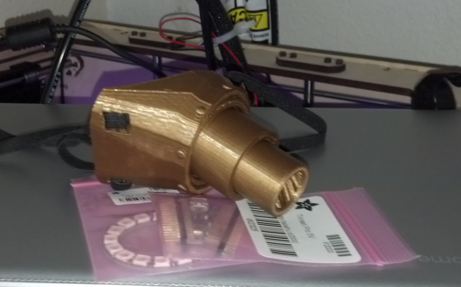
There is probably a sweet spot between enough threads to keep the blade in aligned, but not so many that the extra friction causes the blade to bind. 3

  3. My thinking about the height of the blade isn’t just belly button gazing.  If we know the height of the blade and the amount of desired rotation for the blade to extension, we should be able to define and calculate the slope of the screw threads and sizes of the parts of the planetary gear.
    Components of a planetary gear

    If we want a half turn of the base to cause a full extension of the blade, then half the rotation of the planetary gear should cause sufficient revolutions of the sun gear to result in the full extension of one blade segment.  We could probably make a flat sketch of this by estimating the diameter of the ring gear, determining what half that circumference would be, making reasonable choices for the planetary and sun gear, then making reasonable choices for the blade length.

    TwistSaber Gears
  4. There are a lot of interesting elements to the TwistSaber assembly build videos – the designer clearly put a lot of thought into the design.  There are special ways in which the blades slide and lock in against each other, ways in which the planetary gears snap together and hold each other in place, and even a way for the top most internal telescoping / spinning core to connect to the blade tip.  Once all this is done, there are special ways for the grip to be connected using a series of rings.  I imagine that some of this complexity is due to using purely 3D printed parts with zero fasteners.  I can appreciate this since I try to avoid fasteners as well.
  5. One interesting thing I note about the design is that there appear to be holes in the bases of all of the hilts.  I wonder if this is a need to prevent the entire device from being hindered by air flow and suction given the tight blade tolerances.  Given the intricate design elements, clear thought that went into each part and how the whole assembly goes together, I would love to purchase the STL files and wish they were still available for sale.

More thinking and sketches later!

DIY Lightsaber Build
  1. TwistSabers
  2. DIY Lightsaber Thoughts
  3. Wait, haven’t I worked on this before?!
  4. Considering the design elements of a DIY light saber
  5. More Musings on Lightsabers, Mechanical Components
  6. Slow Progress…
  7. Capstan Drives as alternatives to Planetary Gears?
  1. Sadly, I think some of the videos have been made unavailable…  I wonder what they were?!!? []
  2. 250 * 3)-597)/3 = ~ 51 mm of “overlap” for each segment, probably divided equally between the top and bottom portions.
  3. The twist of the base is an interesting aspect to me.  The desired amount of twist ((One video suggests it is a half twist []
  4. The assembly videos recommend copious grease for the tight fitting threads []

TwistSabers

I stumbled across the “TwistSaber” probably six to nine months too late.  Their original Kickstarter was for the STL or printed parts to build one, then they accepted payments through their website for a short time, and now they have a new Kickstarter where only the exterior shells are available as digital files.

I wish I could find the source, but I remember a guy who had designed and showed off videos of his own quick extending and retracting lightsaber many years ago.  That design appeared fairly chunky and didn’t extend far enough to look very impressive.  If I find the source later on, I’ll look forward to adding it here.

Unlike the 3DPrintingWorld‘s fantastic extending light saber1 models, the Twistsaber uses a combination of an interior telescoping screwthread system and a telescoping nontwisting blade, articulated by a small set of planetary gears in the base to extend and retract the blades quickly.  The effect is pretty cool.

This slideshow requires JavaScript.

There was some scuttlebutt about a “real” Star Wars light saber that was going to be used at the Disney theme parks, which appeared to use dual tape measure slides to extend and retract.  However, the mechanism inside the TwistSaber by inventor Thomas Kloucek appears to be easier to implement, no weird parts to source, while still being a bit fiddly to assemble.  The design appears to be intricate and makes heavy use of snap fit parts with close tolerances.

This is exactly the kind of project I would love to print and assemble, but hate to buy as a finished product.  As a product, it would just sit on a shelf.  As a 3D printed project, it would be a thing I built, a story to with it.

This slideshow requires JavaScript.

Anyhow, I wanted to jot down some ideas, links to the various sources, and images I found for future reflection.  The basic idea, internal increasingly large telescoping spiral and external increasingly small telescoping blade plus planetary gear mechanism might be easy to understand, but as with so many things the implementation is where most of the time would be spent.

DIY Lightsaber Build
  1. TwistSabers
  2. DIY Lightsaber Thoughts
  3. Wait, haven’t I worked on this before?!
  4. Considering the design elements of a DIY light saber
  5. More Musings on Lightsabers, Mechanical Components
  6. Slow Progress…
  7. Capstan Drives as alternatives to Planetary Gears?
  1. and other cutting instrument []