DrawBot – A Preview

Drawing Robot - Preview

Drawing Robot – Preview

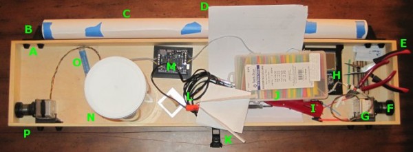
Unfortunately, it will be a few more days yet before I can completely finish the drawing robot.  I still need to order some rainbow ribbon cable and connects, wire up the motors, and then actually draw something with the brand spanking new PolargraphSD brain.  For now, please just ignore the mess of wires and the superfluous Arduino + Adafruit motor shield in the middle.  The blue tape on the paper roll is just there to keep it from unfurling.

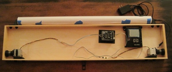
As you can see, the project box looks so much better without all the clutter inside.  Once I’ve gotten everything all set up and tested, I plan to add some internal wire guides to keep the wires in check.  That should help the whole project look a lot more clean and pleasing.

I’m fighting my perfectionist1 to keep printing and reprinting parts.  I had the idea to have dualstrusion printed spools.  I know from experience that rotating single color spools don’t look all that much different that from non-rotating single color spools.  A spool with a dualstrusion pattern embedded in it would provide some kind of interesting visual confirmation that the robot was operational.  Then again, I do like having a very monochrome project – unpainted, unvarnished wood, black ABS plastic, and black oxide bolts.2

You can see above that I’ve already drilled a rough hole into the right side of the box to route the power cable through.  There’s just enough clearance in that hole to allow a USB-B cable to go through as well.

I’ve tried to use a very modular system that allows me to loosen and tighten parts in place with a single bolt.  While making minor adjustments here and there, this system has been amazingly useful.

I’ve taken several more pictures of the various plastic parts and how they fit together.  I’ll post about these shortly.3

Default Series Title
  1. Yes, I do have some perfectionist tendencies… []
  2. Except the shiny M3x8 bolts used to mount the motors.  I wish they didn’t bother me as much as they do. []
  3. Well, to be perfectly accurate, I’ll post about these plastic parts soon.  If you’re a regular reader of the blog, you’ll note that few of the posts could be legitimately described “shortly.” []

DrawBot – A Tour!

Dual use project box

Dual use project box

Above is a picture of my drawing robot, still a work in progress.  The great thing about this particular project box is that it also doubles as a work area.  It’s a good place to cut and strip wires, solder, assemble parts, and it’s totally portable.  The box is 3′ long, 8″ high, 2″ inches deep.

  • A. Printed Bolt Covers.  An M3 nut goes into the recess and the end of the bolt is covered by the printed part.  One of these goes over every one of the protruding bolts in the project box.
  • B. Printed Paper Roll Mounts, on a Slide.  These are actually three separate printed parts.  Since the paper roll came without a cardboard tube, I put a wooden dowel down the center, with printed plastic caps on either side to hold the paper in place.  There are two printed holders which the wooden dowel slot into.  Each of the printed dowel holders slide left and right on a track and have a bolt that can be tightened to keep it from moving.
  • C. Paper Roll.  After looking in a few craft stores I finally found a big long roll of paper at Staples of all places.  I think it was marketed as paper you would use to cover a table.  It’s thin paper, but there’s a lot of it and it was really cheap.  With no internal cardboard tube, I had to design endcaps to keep it from wobbling all around.
  • D. Maker Faire Application.  I’m hoping to display this robot at Maker Faire Bay Area 2013.  Since the call for Makers hasn’t gone out yet I just downloaded the Maker Faire New York 2012 application and filled it out.  Now when the call for Makers comes, I’ll be ready.
  • E. Wire Cutters and Pliers.  These are just necessary tools.  When I need something to hold tiny parts I wrap a rubber band around the pliers and they’re a tiny vise.
  • F. Printed Spools.  Two printed plastic parts plus three nuts and bolts.  Definitely overengineered, but they don’t have the weaknesses of a single print spool.
  • G. Motor Bolted to Motor Mount, on a Slide.  The motors are bolted to a plastic mount with a groove.  The motor mount is then slotted onto the slide which is itself bolted to the actual project box.
  • H. PolargraphSD in a Printed Case. I designed and printed the case.  The way it is mounted to the project box, it is slightly offset from the box, which gives the circuit boards extra ventilation.
  • I. Stick Lighter.  I used this stick lighter to heat the heat shrink.
  • J. Heat Shrink.  Lots of heat shrink in varying colors and diameters.
  • K. Printed Gondola.  This is John Abella’s gondola.
  • L. Soldering Iron.  A cheap soldering iron.
  • M. Adafruit Motor Shield on an Arduino Uno, in a Printed Holder.  Well, that about says it all.  I would point out that the printed holder is pretty terrible – it’s just a little too small.  The only reason I put the Arduino and shield in the box was so that I could hook up the motors and make sure everything was still in operating condition.
  • N. Big Container of Zip Ties.  Zip ties are useful.
  • O. Solder.  For soldering.
  • P. Monofilament Guide.  You can’t see it, but there’s a little plastic tube that fits into a hole drilled through the wood project box.  It’s much smoother than wood and works great.

I’ve taken a lot of detailed pictures of the various parts and how they go together, so that comes next.

Default Series Title