DrawBot – Printed Parts Tour

Drawing Robot - Preview

Drawing Robot – Preview

This is going to be another long in-depth post about my Arduino powered drawing robot.  If you’d like to know more about how to build one yourself, please help me out by filling out my DrawBot poll.  And, if after reading this post you find you want to know even more, be sure and check out the 68 preceding posts about the exact same topic, all listed in order at the end.

While you can build a drawing robot from 95% scrap, it does look better if you have the ability to design and print your own custom plastic parts.  While I’ve discussed my designs for the spools, stepper motor mounts, filament guides, bolt endcaps, and the pieces I use to hold the Polargraph case in place and I’ve taken you on a tour of the robot, I haven’t actually shown you how all the parts fit together.

While I’m quite happy with how everything has turned out, I haven’t had a chance to fire up the robot and actually try a drawing.  Once a few parts arrive from Sparkfun, I’ll be ready to give it a whirl.  Until then, please forgive me for not sharing these designs yet.  It’s less out of a desire for perfection1 and more out of desire not to strand some poor soul with some flawed printed parts.  Thus, I beg your indulgence a little longer.  Until then, I’d like to show you how all the bits I have so far work together.2

Filament guide and bolt covers

Filament guide and bolt covers

On the bottom left of the above picture you can see the filament guide – with filament helpfully sticking out of it.  Just to the right of that you can see two bolt covers/endcaps.

The filament guides ((One on the left, one on the right side)) serve several important purposes.  First, the monofilament line does not squeak when running through the smooth plastic filament guide as it does through a hole drilled in a piece of wood.  Second, it ensures that the two ends of the filament are always at a constant, precise distance from one another which is important for accurate and repeatable drawings.  Filament that is just spooling on and off can change position on the spool by a comparatively large amount.3 Third, the filament guides allow me to make sure the filament is flowing out of the box very closely to the back/bottom of the box – to help keep the pen holder/gondola against the wall.  Fourth, they just look nice.

The bolt endcaps serve some practical and aesthetic purposes.  Without these endcaps, the M3 bolts on the inside of the project box would protrude outside of the box beyond where they meet the 3mm nuts.  The protruding bolts can scratch or puncture and also make the overall project look a little raw.  One minor benefit to using these caps is that the force exerted by the bolt and nut as they are tightened against each other is spread out across the area underneath the endcap, leaving less marks on the project box.

For a project that could be easily disassembled, it would be interesting to create a variation on these plastic endcaps that essentially turned them into wingnuts.  As you will note from the upcoming pictures, many of these parts were specifically designed to make modular assembly/disassembly/modification a breeze.  Having had to pull these parts apart and reassemble them for these photos, I can assure you that taking everything to pieces and putting them back together is a cinch.

Exposed filament guide and stepper motor rail

Exposed filament guide and stepper motor rail

In the photo above you will see the filament guide once I’ve pulled it out of the hole in the project box.  I believe all I did was drill a 1/4″ hole, design the part to fit, press-fit the guide in place, and run the monofilament line through the guide.  I had to re-print these since the first pair was just a little too short.  Ideally the guides should just barely stick out from the project box, so that the monofilament never has to come in contact with the wood.

Once I get the ‘bot up and running, I plan to try using some endstops for automatic homing and printing.  I’ve seen several drawing robot designs that use metal contacts or simple switches to help the ‘bot automatically home before printing.  I think I prefer the style where metal contacts would go around the filament guides at either end, as they are less obtrusive on the exterior of the project box.

Just to the right of the tiny filament guide, you’ll see the plastic rail that I’m using to mount the stepper motors.  There are holes in that long plank of plastic with recesses for the M3 boltheads.  This rail or track or slide is held in place quite firmly by just those two bolts.  Once the rail is in place, the motor mount can be slid back and forth.  It’s a tight fit and would probably stay in place by itself, but why leave things to chance?  The motor mount includes a bolt and captive nut behind the motor, so that it can be tightened against the rail.

Stepper motor, fully installed

Stepper motor, fully installed

In the photo above you can see the stepper motor completely installed.  It’s not much to look at, but I rather like it.  You can just barely see the bolt just behind the motor that I use to keep the mount on the rail.  The setup is pretty solid and more than enough for the amount minor operational stresses they will endure.

Stepper motor, bolt loosened and off rail

Stepper motor, bolt loosened and off rail

In the above photo you can clearly see the top of the filament guide sticking out of the project box, the motor mount removed from the rail, the loosened bolt I use to keep the mount tight against the rail, and the corrugated cardboard I’m trying out for sound insulation.

Stepper motor off rail and spool off motor shaft

Stepper motor off rail and spool off motor shaft

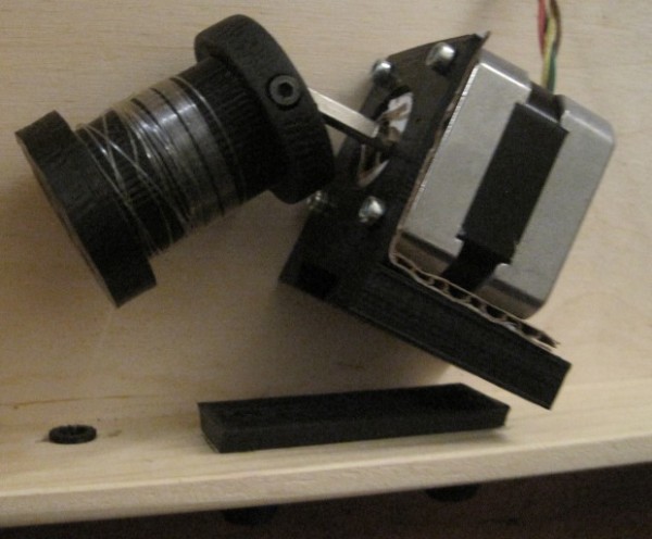
In this view you can clearly see the bolt in the side of edge of the spool I use as a “set screw.”  The end of the spool has to be as thick as it is in order to accommodate the captive M3 nut.  While the other end of the spool does not have to be nearly as thick, I designed it to be symmetrical.4 You’ll also notice that the spool is not tapered on either end.  I designed the spool to be a two-piece bolt-together design.  This has the beneficial side effect of allowing me to trap the end of the monofilament line between the two pieces, rather than using a knot in the filament or some other such fix. ((OCD again))

End of spool

End of spool

Above you can see the end of the spool.  This is the part of the spool facing away from the motor.  Since I didn’t want the spool to be too unbalanced5 I didn’t want to use just one bolt on one side of the motor shaft.  I couldn’t use one bolt down the middle, since it would make the entire spool much longer than necessary.  Given that I was trying to make wide-diameter spools anyhow, it was little hardship to add a way to bolt the spool together on each side.  The end you see has two hexagonal holes to fit the M3 nuts and the other end has long holes going most of the way through, specifically designed to work with some of the M3x16 bolts I have lying around.

Paper roll mount

Paper roll mount

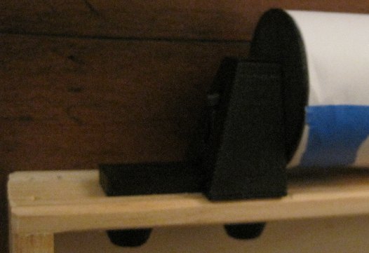
The paper roll mount system you see above were actually the first plastic parts I designed and installed into the project box.6 The entire assembly is pretty solid.  You’ll notice I used another set of bolt endcaps to keep the bolt threads from sticking into the project box.  While I didn’t anticipate them scratching or puncturing anything inside the box, I do really like the way they look.

Paper roll mount, disassembled

Paper roll mount, disassembled

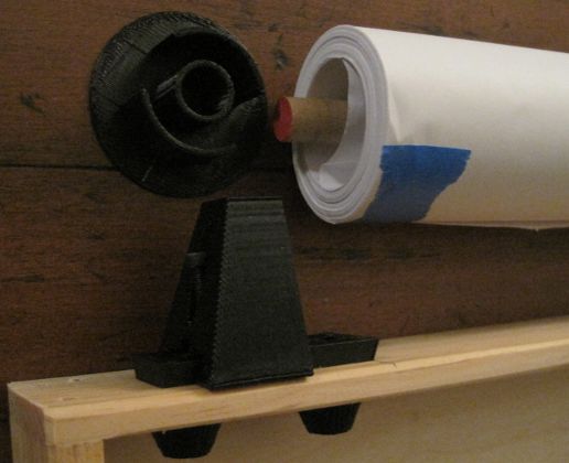
Above you can see the paper roll mount system disassembled.7 The bolt is simply loosened, allowing the piece of plastic which has a circular hole for the wooden dowel to slide back, in turn allowing the paper roll to be removed easily.  You’ll note that the paper roll does not have any kind of cardboard core, as a roll of wrapping paper might.  This is why I had to create the thin endcap for the paper roll.  It serves to keep the paper roll centered on the dowel while preventing the paper from slipping from side to side.  The plastic rail for the paper roll mount is the same exact rail, only slightly shorter, that I used for the motor mounts.

PolargraphSD case installed

PolargraphSD case installed

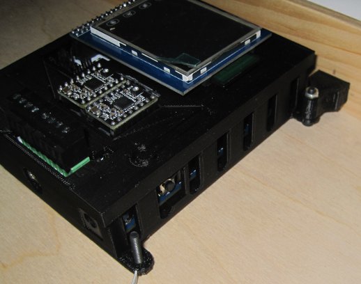
When I designed the PolargraphSD case, I was mostly concerned about creating a case that didn’t use a lot of plastic and which could be easily mounted.  What I didn’t take into account was how I would end up mounting it to the inside of this particular project box.  In the end I had to design two plastic parts that would connect to the PolargraphSD case.  The beneficial side effect is that now the entire case is set off from the back/bottom of the wooden project box by the thickness of an M3 bolt head on each of the four corners.  It remains to be seen whether the vibration of the stepper motors would case the case to rattle.

Don’t forget to take a minute and fill out my DrawBot poll so I’ll know what to blog about next!

Default Series Title
  1. Perfection is the mind killer.  Perfection is the little-death that brings total obliteration. []
  2. Well, hopefully work together []
  3. I would estimate perhaps 10mm or more, depending upon your spools []
  4. Such is OCD []
  5. Like it’s designer []
  6. Sorry for the grainy photo []
  7. Hence, the caption []

DrawBot – The Assembly, Part VI

Okay!  It was a good day for drawing robots in the MakerBlock household!  Here’s what we got accomplished:

  • I designed some motor mounts, printed one… and had to redesign it.  Gotta love having a 3D printer!
  • I selected a long shallow pine box to hold the motors and electronics.
  • I tried a variety of sound insulating materials.  Bubble wrap was easily the most effective, but least practical.  I settled on some corrugated cardboard.  I placed some cardboard between the motor and the motor mount and between the motor mount and the wood.
  • I soldered some longer wires to the motor leads.
  • I drilled holes in the wooden box, attached some monofilament line to the spools, put the spools on the motors, mounted the motors, ran the leads to the Arduino, powered it up… and it moved around and stuff!

As this point the next step is to mount it on the wall and actually attempt to draw stuff.  Yay!

Default Series Title

DrawBot – Design Considerations

This post isn’t really so much of an update as it is a way for me to jot down some thoughts about this DrawBot and to keep me occupied. 1 23

  1. Stepper motors mounts
    1. Right now I’m designing some rather mundane stepper motor mounts.  They’re inspired by Ed’s designs, but I’ve written the code myself.  I’ll post the code on Thingiverse once I’ve printed it.  It will output a good looking motor mount, but the design isn’t entirely parametric yet.
  2. Beaded cord, belts, and filament, oh my!
    1. If you check out this Polargraph video, you can see @ 0:22 where Sandy Noble shows a version of his Polargraph operating using two spools winding and unwinding filament.  The versions Sandy was producing for sale used a beaded cord.  The Der Kritzler uses a toothed belt.
    2. There are several downsides to using beaded cord4 or toothed belts.  First, they’re more expensive and slightly more work to obtain than simple mono filament line.  Secondly, they are both bulky.  If you’re using beaded cord or a toothed belt, they’re going to have to dangle off the side of your machine.  This means more moving and swinging parts – which is a whole other problem.
    3. One of the benefits to using a filament line is that you can easily route and redirect the line using pulleys.  This means that you could mount the motors and electronics in close proximity to each other – and then run the filament line through something like an eye bolt or a specially designed5 part.
    4. I don’t know how any of these options would affect the placement and usage of a servo for penlifts.
  3. In a box6
    1. I have this long shallow pine box, at least three feet in length, that may be perfect for this project.  I think I’ll be able to mount the motors, electronics, and just about everything I need entirely inside this box.  If I do, then all I’ll need to do later is mount the box to the wall, plug the USB cable into a computer, plus the power adapter into the wall, and start printing away!  Now, I realize that this implies a totally vertical drawing surface, but I think that is not as much of a problem as it could be.
  4. The Russians used a pencil
    1. Writing on a perfectly vertical surface with a pen can be challenging.  My thought is to create a gondola that has the weight farther back on the gondola – so that it is pushing the pen against the paper.  If the pen were angled down slightly, this might even work a little better.   But, obviously, I’ve never tried any of these variations.  I have to imagine that smarter men than me have considered and discarded these designs.  I have a crappy sketch for this, but I’m really tired and should get some sleep.

To sleep, perchance to dream.  Ay, there’s the rub.

Fear not gentle reader.  If history tells us anything, tomorrow shall bring your RSS feed another deluge of nonsense!

Default Series Title
  1. I don’t feel like working, even though the hour grows late and I will need to get a bunch of things done one way or another. []
  2. And, really making a drawing robot is SO much more productive than what I do on a daily basis. []
  3. I wish I were kidding. []
  4. Either metal or plastic []
  5. Perhaps printed?! []
  6. With a fox! []

My Ultimate Bag

Bag without notes

Bag without notes

In college I used to carry a camera bag where I kept my stuff.  Car keys, notebook, pens, pencils, etc.  This was an old faux-leather camera bag my dad used to use years ago.  I loved that thing.  Unfortunately, it was stolen out of a friend’s car while we were at a concert.

Over the next few years I thought about what I liked about that bag, what I liked about other bags I had seen, and what I would want in an ultimate bag.  I wanted a bag made from tough canvas, hopefully as tough or tougher as denim, and preferably a khaki color.  I ended up going with a relatively thick canvas from a fabric store.

I also wanted a bag that was big enough to accommodate a full size 3″ binder (the type I thought I might use in grad school), small pockets, wide pockets, a large pocket, and a spot for pens and pencils.  It has thick nylon straps around the bag for holding it together and surprisingly expensive plastic buckles.  I sewed the entire thing with khaki colored upholstery thread.

Bag with notes

Bag with notes

If I were to re-make this bag, I would change several things:

  1. I would try to put the pen holder flaps horizontally rather than vertically.  When the bag is mostly empty the vertical pens poke the bag flap upwards.  I think the bag would probably fit better if pen holders were horizontal.  It would also make it easier to reach in and grab a pen when the top flap is buckled down.
  2. I think it would be pretty useful to have one or two small pockets on either side for stowing away a pen on the outside of the bag.
  3. I don’t really ever use both long pockets.  I’d probably nix one.
  4. I’m always using the four small pockets – they’re incredibly useful.  I’d definitely keep those.  However, I think they might be even more useful if they had a velcro flap to keep them closed.  I have a feeling velcro is a lot easier to attach than zippers.  On top of that, zippers can jam – velcro is basically all good.
  5. I would make the large interior pocket a little wider.  It’s about four inches wide – it could be widened to about six or so.
  6. I would absolutely, positively print all of the plastic buckles on my MakerBot.
  7. I would add a plastic lanyard/carabineer/key hook.  Sometimes I want to toss my keys in and don’t want to worry about them bouncing out (not that they ever have).
  8. When I sewed it together I used a setting on the sewing machine that put the thread seams really close together.  With the thickness of the thread and the closeness of the seams, this ended up essentially making perforations in the cloth.  I would still use thick canvas and thick upholstery thread, but I would set the seams to be wider apart.
  9. I’ve often thought that the bag would be a little better if it were lined or reversible.  If I’m going to line the bag, I might as well make it reversible anyhow.  If I did this, I would make one side black and one side khaki color.  I’ve used this bag as a pillow more than once – and having two layers would make it more…  fluffy.
  10. I’ve been caught in the rain with this bag on more than one occasion.  While this has never been much of a problem, I think a thicker canvas (perhaps the kind used as a painter’s tarp – the kind that’s partially sealed with plastic and/or rubber) would make an excellent water repellent version.
  11. I’ve taken to carrying zip ties in my laptop backpack.  They’re just always useful.  I think it would be nifty to have a long thin pocket where I could stash a few of these.  They would take up practically no room and also act like ribbing.
  12. Have you ever taken a good look at those luggage tags at the airport?  Whenever I go to an airport, I always snag several of them.  They are springy and very very difficult to break.
  13. I would definitely use a much wider carrying strap.  I think something about three inches thick would be ideal.  Perhaps seat belt strap material?
  14. What about a spot for sticky notes (already there in the small pockets), a cell phone, sunglasses, bluetooth, or camera?  Maybe a spot for my sonic screwdriver…
Custom Every Day Carry Bag
  1. My Ultimate Bag
  2. Custom Every Day Carry (EDC) Bag
  3. Sewing Practice
  4. EDC Bag Materials, Designs, Etc