Printable Prosthetics: A Mock Hand

More progress on a fully parametric prosthetic design

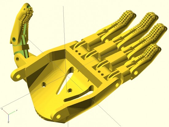
Here you can see the fingers placed appropriately with the palm. I’ve used the same “finger” designs to add a thumb.

For right now, this is just to demonstrate the progress so far.  Theoretically, the only thing left to do is crank out an appropriate gauntlet to bring the entire design together.  In reality, there’s still a fair amount of work to do.  The design for the prosthetic palms was… not elegant.  Also, I want to create a separate (but very similar) design for the thumb.1 It is possible that if I improved the finger designs, I might be able to get away without designing a separate thumb.

In the meantime, I think it looks good and would probably be functional as-is.

Onwards and upwards!

Default Series Title
  1. I feel like the thumb should be stubbier, so I’ll go back and adjust the designs accordingly. []

Printable Parametric Prosthetics: Design Features

Parametric fingers - different lengths, same scale, with no distortion to hardware
Parametric fingers – different lengths, same scale, with no distortion to hardware

I’m not ashamed to admit it – I’m proud of these parametric designs like few of my other designs.  I’ve worked to make this design as customizable and organic as possible.  The two modules that define each finger can be customized in two important ways – they can be lengthened1 as well as scaled up or down – without any distortion or change in the size of the holes for the hardware, elastic cords, or tension cords.

Parametric fingers - with grippy bits
Parametric fingers – with grippy bits

Being able to lengthen2 the finger segments is important because it allows the user to create fingers of different lengths, as normal fingers are of different lengths, all without having to actually scale the fingers to different sizes and without causing a change in each finger’s diameter.

As I’ve discussed in earlier posts, being able to scale the parts up and down without distortion to the hardware holes is important because it allows users to use standard hardware throughout different designs.

For now, it’s back to work on the parametric palm to ensure a proper fit with these parts.

Default Series Title
  1. Or shortened []
  2. Or shorten []

Measurements Required for DIY 3D Printed Hand Prosthetics

Cyborg Hand v7.0
Cyborg Hand v7.0

I’ve recently embarked upon a quest to create a parametric version of the e-NABLE prosthetic designs.  I’ve chosen the “Cyborg Beast” as it came highly recommended and I had the good fortune to meet one the main designers.

I have a habit of diving headfirst12 into a project I know absolutely nothing about and learning just enough to be dangerous as I go.3 Even if the results aren’t what would be called “successful” under normal circumstances, they do tend to be entertaining.

I generally get started by asking a ridiculous amount of questions.4 I have some guesses, but no concrete answers to the below.  If you know, I’d greatly appreciate any comments or replies.  Here’s a bunch to get us started:

  1. What are the minimum required measurements to create a suitable prosthetic, such as the Cyborg Beast?
    1. Knowing the minimum required measurements would allow a designer to better create a parametric design.
    2. The Cyborg Beast instructions refer the builder back to the measurement instructions for the Snap Together Robohand by Michael Curry aka Skimbal. These instructions indicate that all you need is the measurement of the width of the hand, where the hand is held flat with the fingers together, at the widest point on the knuckles.  Based upon the ratio between the subject’s knuckles and the stock Robohand knuckle block, all of the parts for the model are then scaled up or down.
    3. The ease of reference, the entire set of instructions for the Snap Together Robohand are as follows:
      1. Measure the length of the individual’s knuckles across the back of the hand

      2. from the index to pinky finger. (Example: 85mm)
      3. Add 5mm to your measurement to account for the thickness of the gauntlet.

        (Example: if the individual’s hand measures 85mm knuckle-to-knuckle, add 

        5mm for a total length of 90 mm).

      4. The knuckle block in the files you downloaded is 65mm. Divide your result by 

        65. (Example: 90/65 = 1.38).

      5. Multiply the answer times 100 to get a percentage. 

        (Example: 1.38 x100 = 138%).

      6. Scale all the parts of Robohand by this percentage before printing. This can b

        e done using the ‘Scale’ tool in Makerware.

    4. Are there any other measurements, besides the width of the hand at the knuckles, required to create a suitable custom prosthetic?
  2. How do these measurements inform a customized prosthetic design?
    1. Scaling all parts equally makes sense for a “snap together” design where all the parts, including the fasteners, are sized together.  When one is using stock parts (such as screws, elastic cord, and nylon cord)), this approach can end up requiring the builder to do a lot of post-printing work widening holes or trying to find wider screws.
    2. Other than scaling all parts equally, based upon knuckle measurements, is there any other modifications to the printable design required in order to create a useful prosthetic?
  3. How accurate do these measurements need to be in order to create a suitable prosthetic?
    1. Do the measurements need to be down to the micron?  Is within about 1mm or so good enough?
  4. For each required measurement, is it better to round it up or down?
    1. If the only required measurement is the width of the knuckles at the widest point, I suspect that it is probably better to round this figure up, rather than down.  I believe it would be much easier to add a little extra padding or tighten the velcro strapping a bit more.
  5. What are the important structural features of the Cyborg Beast?  As in, what parts, dimensions, and part relationships are absolutely critical to its proper function and fit?
    1. I’m very very weak in this area.  I just don’t know which parts are “load bearing” and are so critical to the function of the device that I should make special efforts to replicate them in my design.  Any suggestions here are greatly appreciated.
    2. I suspect that the critical functional features include part thickness (especially where separate parts meet – for strength and durability), the height and length of the “outcropping” on the back of the wrist which appears to provide the mechanical advantage which causes the fingers to constrict, and the tightening block on the gauntlet.
  6. What are the important design features of the Cyborg Beast?  As in, what parts, dimensions, and part relationships are critical to the suitability of this model over others?
    1. Again, I’m incredibly weak in this area.  I suspect that the overall organic shape to the model is one of its most stand-out features.  However, I would invite more informed comments and observations.
  7. What parts of the Cyborg Beast are the most improved?
  8. What parts of the Cyborg Beast are most in need of improvement?
Default Series Title
  1. Almost willy-nilly, if you will. []
  2. You will, won’t you? []
  3. I imagine this is what it is like to learn to fly. []
  4. If you don’t believe me, feel free to peruse this site where you fill find literally thousands of words on the smallest design variations on the smallest parts for a drawing robot []