Building a Travel Ukulele: Back to Basics

This slideshow requires JavaScript.

My experiment with a multi-piece turn around didn’t work.  The idea was for a multi-segment turn around where each string could be tightened and that portion of the turn around would be able to rotate as needed independent of the other pieces.  I simply did not account for the kinds of stresses the pieces would be under through normal use and string tension.  Each segment deformed, resulting in none of them being able to rotate and the slightly less rigid turn around bowing slightly under the pressure.  I couldn’t get a great picture of the deformed parts, but perhaps this will give some idea.

This slideshow requires JavaScript.

In the end, the best result for my ukulele has been a 3D printed turn around, finely sanded smooth, unadorned by paint, with a small amount of lubricant (I’ve used machine oil) over the metal bridge and across the turn around.  These simple elements have, hands down, beat the over engineered / over designed pieces above.  If they were printed out of a more rigid material, milled or turned from solid metal, created by using a system of washers, or made using a full length bolt, I’m sure it would have worked better.

The design of my turn around uses captive nuts in the plastic core, secured by bolts on either side.  This ends up being dramatically easier and cheaper than trying to source very long Chicago bolts and posts – but has a minor downside in that the two bolts don’t actually connect.  As long as the material between the two bolt ends is strong enough to withstand the continued forces of four strings under tension, there shouldn’t be a problem.  However, even printing the turn around with the best orientation for printing strength in PLA didn’t result in a part that could withstand these forces for a long time. 1  One of my ideas for this part involved using bolts that were possible slightly longer or of different lengths so they would both tighten slightly into the same captive nut, resulting in one “continuous” piece of metal for the turn around core, then using washers to ensure / assist in minor distance adjustments.

Here’s how it looks today:

This slideshow requires JavaScript.

I don’t plan on any more improvements for this particular ukulele.  I’ve deeply enjoyed playing it since it became “finished enough” to be playable in August of 2022.  That said, I’ve been thinking about how I would create another one.

  1. CNC Cut Wood.  I spent the vast majority of the time on this project just rough cutting the wood to size using a combination of hacksaw and coping saw blades.  I spent a ton more time shaving wood off the neck using rough files.  Starting with a piece of wood that was already the approximate dimensions and only needed finishing would feel like starting at the 90% mark.
  2. Different Wood.  I went with mahogany for a variety of reasons – but cost was one of the biggest and dumbest of these.  The difference between a plank of mahogany for $10 and the most expensive wood from Rockler at maybe $30 is a rounding error when the project took more than 100 hours of my time.  I’ve suggest that wenge, zebrawood, ironwood, or walnut would be my choice for another attempt.  Of these, I am leaning towards walnut for a deep brown, possibly gray finish.
  3. Strap Attachments.  The strap was not quite an afterthought.  I had always planned on using nylon webbing / seat belt material for the strap and had designed printed strap buttons for hooking the strap onto the ukulele, but in the end I just couldn’t bring myself to drill holes in the finished uke.  This was just as well since I had wanted to try using some paracord in a project for a while.  After using a flame to seal the ends of the paracord and webbing, the result was way too thick to use in my sewing machine and had to be hand stitched.  I’m not great at hand sewing, but it is functional.  Given the dark colors of the thread, paracord, and webbing, the haphazard stitching isn’t very noticeable.  If I really took my time with it I might be able to do a better job.  If it came to that I might want to use some silver or light gray thread to add a little pop.
  4. Acoustic Improvements.  I’ve noticed a dramatic change in the quality of the ukulele sound when I place a book, empty box, or large piece of rigid cardboard between the uke and myself while I’m playing it.  I’ve thought about how this could be incorporated into a new design by creating a system for bolting, attaching, or otherwise connecting a larger section to the ukulele.  Another incredibly interesting option is the plastic sheet used by TitchTheClown.  He used thumbtacks to secure a sheet of plastic from a soda bottle against the ukulele, then a heat gun to tighten it into something like a drum surface.
  5. Other prior improvements per a prior post.
Default Series Title
  1. I’d say it took about six months for the deformations to become noticeable []

Printable Prosthetics: Brainstorming

An illustrative hand

An illustrative hand

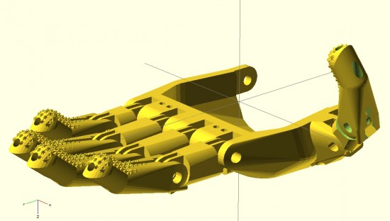
My overall designs for a printable parametric hand are still far from done.  And, yet, I’ve come a long long way since jumping headfirst into the realm of open source prosthetics a little more than 30 days ago.12

Forgive the digression, dear reader, before I return you to considerations of prosthetics. After visiting the Asian Art Museum today with the family, I am feeling particularly inspired to discuss dualities.3 I find I am an often-inspired person. This is a very charitable way to describe myself by what would otherwise colloquially and clinically be considered ADHD. When I am inspired by a new topic, I tend to jump right into it – reading voraciously and trying to learn as much about it as I can. When this happens, I also tend to set aside whatever thing I was most recently working on. This means that recently I’ve done little work on drawing robots (big and small) and a multitude of other small projects that would otherwise be just amazing. However, such inspirations/distractions are not only external to a project – but can also be very much internal to a project. Consider, for instance, feature creep – the adding of ever more features to a project, usually at a faster rate than which features are resolved and refined. In order to combat this aspect of my nature, the wanting to add more and better features, I have developed a coping mechanism. To prevent myself from falling down the rabbit hole of features and improvements, I jot them down someplace – either in a blog post4 , in an email to myself, or in a notebook.5 I find that once I’ve externalized and memorialized an idea, I can continue working on a project unfettered and undistracted these other ideas.

To this end, and in the spirit of open source ideals, I will jot down some ideas while I have them:

  • How large and how small are prosthetic designs typically scaled?
    • I wanted to have a range of sizes for which my designs were optimized.  My guess would be no smaller than 85% and not much more than 160% of the size of the existing  Cyborg Beast.  Jorge Zuniga was, again, patient enough to discuss this with me.  His estimate of a range would be between about 105 – 150%.
  • What is the diameter of the Chicago Screws typically used in the creation of a Cyborg Beast?
    • From the retailer’s website, it appears the “barrel” diameter is 0.2 inches, or 5.08mm.  I’ll need to make some adjustments to holes for the Chicago Screws in the designs.
  • How important is hyperextension of these fingers?
    • The designs of the Cyborg Beast include fingers that can bend “backwards” very slightly.  Each finger joint includes a “stop” at the back of the joint.  While certainly useful, I question their necessity.  I previously designed a connection system for printable snap-fit parts ((For use in an equally noble project)) that connect very tightly and/or bend with a user specified degree of movement.  The point with me mentioning these parts is that the “stop” used at the back of each knuckle and joint in the Cyborg Beast may not be necessary at all.
  • How necessary are metal Chicago Screws to strength and durability of the hand and fingers?  
    • Before you laugh, consider this question – what is the weakest point of any given finger which uses a metal Chicago Screw when having to deal with lateral forces?  I would postulate the weakest points would be those thin plastic parts surrounding the Chicago Screws themselves.  Thus, even though the hand incorporates metal pins, I have to wonder just how much strength they are providing to the overall device.  It would be easy to conceive of a plastic prosthetic hand that was so small that there wasn’t a lot of plastic around each metal screw6.  In such a case, the weakest points would be plastic surrounding the metal parts.  Extending this conjecture, of what use are metal fasteners to a design that is primarily plastic?  The best guess I can offer is that they allow reliable and smooth operation.
  • Work on proportional fingers
    • In designing the fingers, I worked to be able to make them customizable in several different ways.  The user may specify whether the fingers have the “star grip” pads, whether the finger should be slightly shorter or longer, and scale the finger up or down – without distortion to the hardware and cord channels.
    • I need to add at least three additional options to these parametric designs.  The designs should include the option to add “mouse ears” and easily removable support structures.  Additionally, the design should also allow the user to change the diameter of the finger.  I did implement this, somewhat, in part of the design.  Without implementation throughout the entire design, these partial attempts aren’t helpful.
    • In creating the fingers shown above, I adjusted their lengths to conform to the measurements of my own hand.7 Next time, I think I would also measure finger diameters.
    • I think I should create a way to prevent finger parts from being mixed up accidentally while printing.  A possible solution is to include “mouse ears” with each finger – but embed an identifying mark in each mouse ear to label the parts.
  • Ideas on making a better parametric palm
    • The palm should be redesigned so that the fingers, at the appropriate lengths, would fit into it.  I designed the fingers quite a while since working on the palm.  I haven’t had a chance to ensure the parts would mesh well without adjustment to the scale.
    • On an entirely different note, I have an idea to redesign the entire palm.  By carefully placing deformed spheres, I was able to design a palm.  Using a similar process, I subtracted out a void for the user’s hand.  The result is a palm with an uneven thickness throughout.  Uniform thickness isn’t necessarily an interesting or useful goal.  That said, it could lead to a reduction in unnecessary plastic.  If I were to redesign the palm, I could design the internal area first8 – and then use the “Minkowski” function to create a uniformly thick shell around the internal form.  The bottom would have to be sliced off and the original internal area would need to be subtracted from it.
  • Ideas on making a more realistic hand
    • My designs so far are based primarily on the Cyborg Beast, with some minor changes.  The “Flexy-Handappears to be very organic and realistic.  It also features flexible printed connections between each finger segment.  Additionally, each finger is comprised of three segments – rather than two like the Cyborg Beast.  Interestingly, since the flexible connections between segments allows the hand to return to an “open” position, the hand only requires five tension cords – rather than five tension cords and five elastic cords.  The fingers appear to not have any “stops” behind each joint.  I have to wonder how having three segments to each finger impacts the function.  Does it allow the hand to better grip things?  Does it make the hand less sturdy?
  • Masculine/Feminine hands
    • One well-intentioned comment to my latest designs is that they are “pretty.”9 While I accept the compliment with the spirit in which it was given, it immediately made me wonder – is the hand I designed “feminine?”  Then it occurred to me that with more design effort, I could make “feminine” and “masculine” version of these hands.  I think the primary differences would be two-fold – thinner fingers and a less “hefty” palm for a more feminine version and a thicker and perhaps more “blocky” palm for a more masculine hand.
  • New developments
    • There have been a number of interesting and new developments and experiments of late.10 In no particular order, these ideas are:
  • Discussions with a 7-year-old
    • A few days ago my daughter and I were jotting down some ideas in my sketchbook.  As we did so, she saw some of the notes from the e-NABLE meeting on 3/21/2014 – including several sketches.  We discussed the problem – affordable, customized, and comfortable prosthetics.  We talked about amniotic band syndrome, how fibrous amniotic bands affect fetuses, and the different ways in which these bands can cause11 deformities to single fingers, whole hands, and a range of changes in between.  I explained how Mr. Jose Delgado Jr. had a $42,000.00 myoelectric prosthetic, the problems he has with that prosthetic, how and why he prefers his $50.00 printed replacement, and how for the price of his one prosthetic people could make 840 more prosthetics.12 She asked, “Why can’t someone use a stump to operate a hand?” I replied that this was exactly how these prosthetics worked – and I drew a few simplified sketches of the Cyborg Beast.  Her next question was, “Why can’t it move side to side?”  I said that Mr. David Ogreman had designed such a prosthetic.
Default Series Title
  1. My first concrete step was going to an e-NABLE meeting in San Francisco on 3/21/2014. []
  2. The above picture is slightly misleading.  I haven’t confirmed that the fingers I’ve designed will properly fit into the palm that I’ve designed – or that the thumb would work at all.  Thus, the picture is partially a parlor trick and partially an indication of where I hope to take this design. []
  3. Many of the gods and goddesses in Eastern religions embody dual natures – creation/destruction, life/death, etc []
  4. In one of my several different blogs. Besides, what could be more ADHD than having 3+ blogs?!? []
  5. You may not find this as amusing as I do – but I probably have about four different sketch/notebooks. []
  6. Say, only 1mm []
  7. From pinky finger to thumb, the non-scientific measurements from knuckle to finger/thumb tip were 77mm, 102mm, 106mm, 92mm, and 72mm []
  8. Using the deformed spheres and hull trick []
  9. Thanks Erik! []
  10. I don’t even know why I’m saying “of late” when I’ve really only been involved a little over 30 days.  I guess becuase these developments are new to me? []
  11. Please forgive my lack of a more politically correct term.  If you’ve got a better or more sensitive phrase, please let me know as I will gladly adopt it []
  12. She wanted to know if he could get a refund! []

Printable Prosthetics Fingers and OpenSCAD Design Tips

Solid finger tip for Cyborg Beast

Solid finger tip for Cyborg Beast

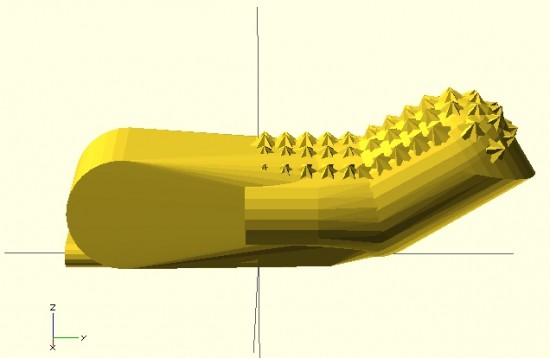
Above is my first attempt at designing a “solid” finger for the Cyborg Beast DIY printable prosthetic in OpenSCAD.1 The reason this is a “solid” finger is that I haven’t subtracted out any material to allow this partial finger to connect with anything else.

The problem with scaling (up or down) any design that requires fasteners and hardware is that when you do, the holes for the hardware are similarly scaled.  This leads to more post-printing work drilling holes to widen them or to find larger fasteners that won’t rattle around in too-large holes.

Thus, if the hardware consists of 3mm screws, the holes for the hardware should be 3mm no matter how much the parts are scaled up or down.  To make matters more interesting, not all holes in the model should be excepted from scaling.  The above finger tip has a plastic end that is supposed to fit into a mid-finger piece – and those parts should be scaled up or down according to the size of the overall hand.  Thus, some voids should be scaled2 and others not at all.3

I’m rather happy with how this finger has turned out so far.  It has most of what I understand to be the essential features of the Cyborg Beast fingertips, including little nubs along the finger pad to allow for gripping.  I intend to make this an option, in case a user would rather use something like Plasti-Dip to make grippy finger pads, rather than relying on printed plastic bumps.

However, converting a decent design into a parametric design requires a little more work.  The way I go about designing a parametric model is to first design one instance of the thing, in this case the finger tip.  My next step is to poke through the OpenSCAD code to locate those aspects parts that contribute to the models’ essential features – length of the finger tip, for instance.  Once I’ve found these bits, I then try to modify them so that I can insert different variables and arrive at sane variations on the model.

Wish me luck!4

Default Series Title
  1. If this is your first time tuning in, check out the prior posts in this series using the links at the bottom of this post []
  2. Where parts meet []
  3. Such as holes for hardware []
  4. See, this is a post about finger tips and design tips!  Oh, man, I crack myself up! []

Skipping! How could I forget the skipping?!

Hubris, I haz it

Hubris, I haz it

Mr. Noble is not the only one prone to hubris.1 After taking into account every post on ideal drawing robot pen holder criteria, I found one more post that I should have read first.  Dan Royer of MarginallyClever.com suggests2 as good pen holder should:

  1. A single cord convergence point.  “Have the two strings meet at a single point, or as close as possible.  The moment they separate the math gets really ugly.”
  2. Deal with friction.  “Friction causes the pen to drag and lean.  If I tell the robot to draw a square corner and it comes out rounded then I know my pen is dragging because it never reached the corner.  The pen has to stay at a right angle to the drawing surface.  So far I’ve found that having at least three points of contact is enough to eliminate the problem.  That’s why I tape my business card to an eye bolt on the bottom of the ring – the bottom edge of the card forms a large contact area with very little friction.”
  3. Be well balanced.  “If the pen is balanced wrong it may point up or down.  If it points up then it might go dry.  If it points down then it might have extra friction when moving downwards, causing the pen to skip and create a dotted line.”
  4. Have an easy way to switch pens.  “Not only should it be easy to replace a pen but every pen should “lock” into the pen holder at the same distance and angle from the drawing surface.  In order to simplify this problem I only use one kind of pen that comes in many colors.”
  5. Works on a slanted surface.  “Works on both vertical and slanted surfaces up to a maximum of 10 degrees.”

My own prior post on ideal characteristics in a pen holder took into account Dan’s number 1, 3, 4 and considered 5.  What I failed to consider was how friction can cause the pen to skip or stutter when the pen is mounted at an angle and the pen travels upwards.

Although I started diving into this consideration, but I’m putting all that over-pontification into its own post.  This post is really about (a) Dan considered a very important factor in pen holder construction which I neglected and (b) how awesome open source is.  My own pen holder would be a terribly complicated mess doomed to multiple revisions had I not had the benefit of being able to review a veritable legion of pen holders used by many many other people in their many many different kinds of vertical drawing robots.

So – Yay Dan!  Huzzah open source!

The next post will be about whether this consideration would cause me to change my existing pen holder design.

Default Series Title
  1. Photo courtesy of Markus Krispler []
  2. I’m keeping all of Dan’s words, but reformatting them []

DrawBot Pen Holder Post Mortem

Yoda, standing tall

Yoda, standing tall

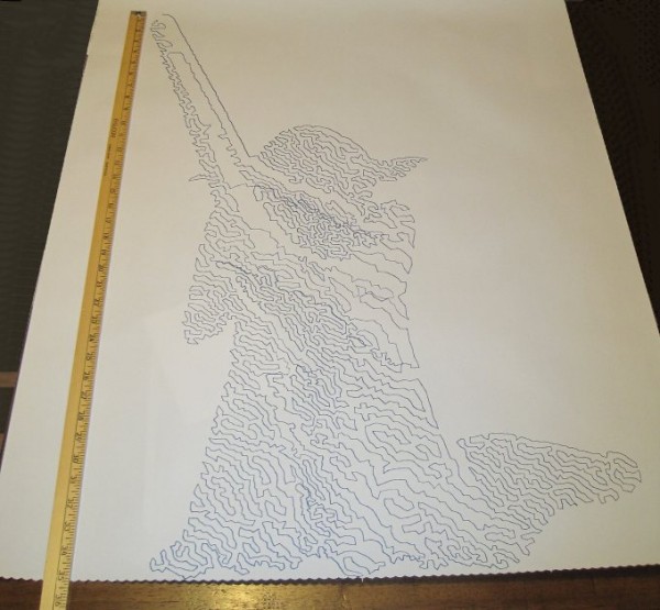
Two days ago I designed a new type of pen holder for my drawing robot based upon what I had learned from examining the pen holders other people have designed and used.

Here’s what worked and what didn’t:

  1. WORKED:  The fit.  I’m really happy with how the pen holder went together.  It’s always very satisfying to print a part you just designed and have it “just fit.”  With the zip tie holding the micro servo in place, neither the micro servo tab nor the zip tie protrude beyond the flat surface of the pen holder.  The groves for the rubber band to hold the pen in place work very well.  The pen doesn’t move side-to-side, get pushed back into the holder, and it is very easy to reposition the pen or change pens entirely.  While it’s not as elegant as, say, a metal spring, it works very well and doesn’t require a bunch of moving parts.
  2. WORKED:  The amount and placement weight.  I hot glued a AA battery to either side of the pen holder, as close to the center as I could manage around the hole for the pen.  This weight seemed to work perfectly.  There was enough weight that the cords hung in straight lines, but not so much that it seemed to cause a strain on the motors.  The placement of the weights seemed to work well as there was no noticeable pendulum swinging of the pen holder, despite me running the robot at about three times it’s usual top motor speed and about twice it’s normal acceleration.1
  3. WORKED:  The multiple points of cord attachment.  Having a row of holes for connecting the cords at different points along the top central edge of the pen holder worked out great.  To test the balance all I did was stick a small paperclip through a hole.  If the holder balanced with the flat edge upright and vertical, that’s the point I needed.  It was easy to find the balance point and easy to connect the cords.
  4. WORKED:  The single point of cord attachment.  When I was using a crappy cardboard pen holder with cord attachment points very far apart, the entire pen holder would tip to one side or another when it got close to that side.  This caused a bubble-like distortion effect towards the edges of the drawing.  While this could be a cool effect to intentionally inflict on a drawing, it’s not what I was going for with that crappy cardboard design.  Having the two cords meet at exactly the same point worked out incredibly well.  Even when the robot was drawing the top left corner of Yoda’s lightsaber, the pen holder was always perfectly vertical.
  5. WORKED:  Shape of pen holder flat side.  The pen holder I’ve designed is roughly teardrop shaped, with a flat top.  My thought with giving it a “flat top” was that it wouldn’t potentially develop a central raised point (between the circular top edge of the pen holder and the device I was using for the pen lift) when I was doing a pen lift.  I figured that if I was using a “flat top” it was possible for the pen holder to be balanced on the edge of the flat top and the point of the servo arm – essentially turning my full contact pen holder into a three point contact pen holder with the servo arm as one of the points.
  6. DIDN’T WORK:  Motor skipping?  There is a large section in the middle of the drawing of Yoda, pictured above, that looks like it was shifted downwards slightly.  This could have been because I was fussing a little with the robot while it was working.  It could also have been because I was running the robot pretty fast (motor speed of 1600 when the normal is 600), because I had increased the acceleration (400 instead of the default 800), because I had the pots turned down too low (maybe, but the current settings have worked reasonably well for other drawings), because the pen holder was too heavy and causing too much strain on the motor (very unlikely since this holder is lighter than the cardboard abomination I was using) or some combination thereof.  My guess is that I probably need to increase the pots when I increase the speed.  It’s really unlikely that the pen holder itself was to blame for these missteps.2
  7. DIDN’T WORK:  The pen lift.  I haven’t drawn anything with a pen lift yet – but I did test the pen lift last night after Yoda was done.  I noticed a few minor problems with the pen lift – but nothing to indicate I was on a completely wrong track.
    1. The first problem is that I glued the two batteries slightly too close to the clearance area for the micro servo arm.  This is why the next version will include a holder for the AA batteries – to ensure they don’t get in the way.
    2. Second, even when fully extended the servo arm didn’t push out far enough to cause the pen tip to lift off the surface of the paper.  This could be solved by either making sure the pen tip is positioned slightly farther back, extending the servo arm, or creating a servo arm powered cam, similar to Dan Royer’s Makeangelo (check out the video at about 4:35 for a view of the cam in action).
    3. Third, my concern is that since the micro servo is mounted in such a way that the servo arm sweeps from right to left, it could cause a similar sweeping motion to be applied to the pen tip – assuming I work out the pen tip depth issues.  It’s possible that sweeping the arm upwards or downwards might minimize this effect.  I just have no idea whether this is a valid concern or not – the servo arm might move so quickly that it’s not a real concern.
    4. Also, while not an actual issue, the servo motor cable applies a bit of weight to the pen holder.  This will require me to reposition the cord attachment points – and may require me to add extra weights to the pen holder itself.

Once I change the pen position and maybe use a larger servo arm, I’ll try a vector drawing which requires pen lifts and re-evaluate this design.  Overall, this design has basically worked beautifully.  I’m looking forward to experimenting with some new variations on the design to see if I can eliminate the few remaining issues.

Default Series Title
  1. I’ll pretend I was doing this for a system stress-test, but really I was impatient to get a big giant Yoda drawing []
  2. Does that count as a pun? []

Enough talk! Finally a pen holder!

Doesn't look like much, does it?

Doesn’t look like much, does it?

I admit it, I’m prone to verbosity.   I wrote 2200 words just discussing the kinds of pen holders other people have used and another 2300 words talking about what I consider to be ideal qualities in a pen holder.1 In some ways, the pen holder is possibly the least important part of the entire robot.  When you can use something like a binder clip or cardboard, hot glue, and dead batteries to create really amazing drawings, it’s almost a waste to spend any time thinking about what makes an idea way to hold a pen.  However, since I’ve got the rest of the robot looking and working just like I always wanted, I’ve latched onto this last part as something I would like to optimize.

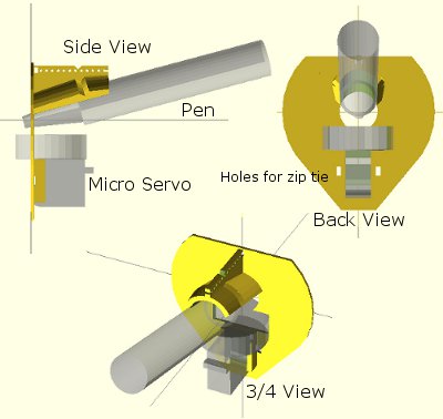
Above is an OpenSCAD rendering of a pen holder I’m getting ready to try out.  As I type these words, my Replicator is a little over 50% done printing the pen holder.  Before my three most recent posts discussing pen holders I had been working on an overly complicated, multi-part, pen holder.  It consisted of several pieces that would be printed simultaneously, several spots for captive nuts – the features went on and on.  Don’t get me wrong – a pen holder like that might be genuinely great – but I’m not sure that level of complexity is necessary or in any way worth the design time.

The design pictured above meets several of my criteria for an ideal pen holder.  For your consideration, I submit the following features, design choices, and design elements:

  • Just one very lightweight part.  This printed part would require only a rubber band to keep the pen in place and, if you’re using a micro servo, a single zip tie to keep that in place.  At the moment the design doesn’t include a space for weights.  Once the part is done printing, I’m going to put it together with the micro servo and pen and see how it hangs.  If it looks okay, I’ll hot glue some batteries to it in various spots.  If that works well, I’ve already got a variation on this design which includes some printed tabs for adding dead batteries for weight.  The part itself uses very little plastic and prints fairly quickly.  
  • “Full contact” stabilizer.  In a prior post I discussed the several types of pen holders and how they can have a single point of contact with the drawing surface, three points of contact, or “full contact.”  While the Polargraph style pen holders use a blank CD (120mm in diameter), the above just uses a mostly round shape 80mm across.  I don’t know if this is wide enough or not, but this is a first draft.
  • Pen held at angle.  Felt pens and markers don’t really require they be held at an angle, but I can’t imagine it would hurt.  Well, I suppose they could have too much ink come through – but I could just run the robot a little faster.  There’s no science behind my choice of the pen tilt at a 15 degree angle, it just seemed like a reasonable number.  Since it’s a parameter in the OpenSCAD file, I can easily go back and change it if this is just a terrible choice.
  • Cord attachment points #3, the “Single cord convergence point, not at the pen tip.”  This pen holder is designed to allow the cords to essentially meet at one specific point – namely one of the tiny holes in a row along the top edge of the pen holder.  These are most visible in the top left of the above picture.
  • Centering point viewer.  Since the cord convergence point is centered on one of those tiny holes, the user of this pen holder can look through a tiny hole the the flat surface of the pen holder to make sure the pen holder is properly centered and homed.
  • Multiple points of cord attachment.  Depending upon pen type, pen weight, and pen holder weight and distribution I could imagine there might be different optimal points of cord attachment.  The top edge of the pen holder has a series of holes through which the cord could be fed.  The way to attach the cords would be to create a small loop in the end of the cord, feed it through one of the holes and then hook it onto the protuberance at the end of the row of holes. (You might have to look at the top left picture a bit to notice this bit). The other cord would be fed through the same hole – just on the other side and hook onto the same protuberance.  This setup was inspired by Dan Royer’s multiple point of attachment set up and the AS220 labs “clip stabilizer.”
  • Pen held securely in place and depth.  A rubber band should do the job of keeping the pen in place nicely.  I added a groove to the top edge of the holder where the rubber band can rest.  I can’t imagine needing a cord attachment point as far back as the groove near the pen holding cylinder, so I fully expect the last four or five holes can be eliminated, which means I can use the groove around the pen holding cylinder as it was originally designed – to serve as the resting point for the rubber band.
  • Multiple pen diameters/pen lengths.  Although this holder was designed for a pen with a maximum radius of 20mm, it could probably accommodate up to 25-30mm.  All but one of the pens in my house would fall in the sub-20mm-diameter category.  The reason for having the rubber band point so far back along the pen is that most pens are tapered towards the marker tip, which means you can’t really hold the pen any closer than 20-30mm back from the tip.  The holder is designed to hold the pen 30mm back from the pen tip, which is enough to accommodate all but the absolute largest marker.
  • Holder for micro servo.  The holder was specifically designed for my micro servo.  Once the micro servo is inserted (in the orientation shown by the shadowy looking micro servo in the images above) one of the tabs for the micro servo sits completely flush with the flat side of the pen holder.  There are holes on either side of the micro servo through which a zip tie can be fed.  There’s even just enough clearance so that the zip tie itself doesn’t protrude past the flat surface of the pen holder.
  • Clearance for the widest servo arm.  I know many others have designed much better mechanisms for having a micro servo perform a drawing robot pen lift.  Since this is literally my very first attempt to incorporate a micro servo into one of my drawing robot projects, I figured I would just use a bare-bones approach and have the servo’s arm directly push the pen holder off the drawing surface.  I’m positive there are more optimal ways to do this but again, this is a first draft.

I’ve uploaded the files to Thingiverse, to be followed by my janky OpenSCAD file.  It started off totally parametric and then as I got close to finishing it, I just started entering in numbers that would make it work.  I’ll go back and improve it, but for now I’ll share what I’ve got.

Default Series Title
  1. I haven’t even started blathering on about different kinds of pens! []

This project is not going to overengineer itself

Seriously, why would anyone with hands buy this?

Seriously, why would anyone with hands buy this?

This weekend I worked on my DrawBot.  ((Photo courtesy of Relly Annett-Baker))  I stripped my current DrawBot for parts so that I may build it back together with a PolagraphSD brain/heart.  ((Bart?  Hain?))  Given that there aren’t a ton of parts involved, the process went quickly.  I disconnected the two steppers, pulled all the screws1 and all the nuts and bolts2 from the project.  Right now all that is left of my once mighty3 drawing robot is an Arduino and shield duct taped to a chunk of plywood.

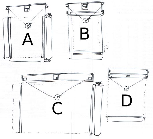
To assemble the new robot into the desired configuration ((Sketch D for those of you playing along at home)) I needed to design:

  • A new PolargraphSD case
    • This new case is about 2/3 the volume of Sandy’s design and has vents along the sides and top to help with heat dissipation.  It can also be assembled without any tools or hardware – with the LCD actually keeping the entire thing together.  At this point I now have three perfectly serviceable cases.  My goal, once the entire robot is put together, is that it look and feel like a finished and polished project – a DONE project.  But, really, I’d like to have it semi-permanently installed somewhere in my house as a drawing appliance.  My prior ‘bot while cool with tons of nifty little hacker cred to it was little more than a chunk of plywood with bits hanging off.  I’d draw something with it, put the board away, then bring it out later.
    • My ideas for building out the robot have changed slightly since designing this case, so I might need to adjust the code and print another one.  The issue now is that the case is designed to be mounted by being bolted into the base of the project box.  However, if I do that a nut or bolt will have to stick through the back of the project which will prevent the paper roll from being able to travel behind the project box.  I figure I could print a new case and bolt it to the side of the project box – but that might interfere with the location of the motors/motor mounts.  I might be able to just ziptie the case to the top of the project box – which might not be good as the bot is expect to shake a little in operation and I don’t want the board shaken unnecessarily.  Frankly, at this point, I think I’ll get everything else situated completely within the project box and come back to figuring out how to mount the case.
    • Although, an idea which just occurred to me is that I could glue some plastic mounts, with captive nuts, into the inside of the project box and bolt the case into that.  Again, this would best be done once all the other issues are resolved.
  • New monofilament spools
    • I had to completely destroy my existing spools to get them off the motor shafts.  For some god-awful reason I printed the two spools at 100% infill creating the sturdiest monofilament spools in existence.  I cannot imagine what possessed me to do this.  They were heavy and impossible to remove cleanly from the motor shafts.  I didn’t get the tolerances right with the prior spools, so I had to force them onto the shafts – but then they were stuck.  I had to use a big pair of wirecutters to chop chunks of plastic off until I could pull the last bits free from the motor.  When I finish designing and printing a new set of spools, I’m going to make sure the tolerances are right before I assemble.  I want the spools to fit snugly becuase I don’t want the motor to slip when it reverses directions – as it will do frequently across a large drawing.
    • I’m still kicking around ideas on how to improve the spools.  My first spools were way too complex and the friction fit wasn’t enough to keep them together.  My second set was too tight and too short.  While I wouldn’t mind a friction fit spool, I need a spool that can’t come apart during operation4 , can be tightened on the motor shaft, and can be removed easily if necessary.  Additionally, I’d like the final spool to be taller – so that there is more of the spool center and less of the flared end of the spool for the filament to wind onto.  The flared end was flared so that the spool could be printed as a single piece.  While this was nice for simplicity’s sake, I found that sometimes the filament line would “ride up” the flared end – which introduces unnecessary error into the process.
    • Looking at the AS220 Labs website page for their drawing robot kit through Archive.org, you will notice that they use a tall spool with a low-friction monofilament line guide.  The benefit of the tall spool is that it can keep a more consistent diameter for more of the filament versus a narrow spool that will accumulate layers of filament more quickly.  The benefit of the line guide is that it forces the robot to maintain the proper distance between the two motors even when the spools are mounted horizontally.  I also happen to like the horizontal spool mount system since it means the motors won’t stick out from the wall quite so much.5
  • A new gondola
  • A way to mount a roll of paper to my project box
    • Besides tearing my drawing robot apart, this is the one thing I did manage to design, print, and put together over the weekend.  Since the paper roll I’m using did not come with a center of cardboard or wood or on any kind of spindle, it is not an immediately mountable thing.  My roll of paper is just that – a really long roll of paper.
    • What I wanted was a modular way to mount a roll of paper to the top of my project box so that it could be adjusted to fit different diameters and widths of paper rolls.  My solution was to print two “caps” to go at either end of the paper roll, with a hole through them to run a long wooden dowel.  The nifty part is where I then bolted two printed plastic tracks to the top of my project box, onto which I can slide a plastic arm which the wooden dowel fits into.  Once the two plastic arms are in place, they can be tightened down onto the plastic track.  The result is a rock solid paper roll mount that lets the paper roll freely turn.  I was so happy with the way this turned out I almost couldn’t see straight.  Yes, it is just a mount for a roll of paper – but it is the most solid and polished way one might hope to mount a core-less roll of paper on top of a wooden box.
  • A new way to mount the stepper motors to the project box
    • Given the amount of time I’ve spent just mounting a roll of paper and obsessing about spools, is it any wonder I haven’t finished thinking about how to mount the steppers?  With the first incarnation of my drawing robot I had designed and printed no less than three completely different motor mounts.
    • I would like the final version of the motor mounts to be easily adjustable, probably using a similar track/mount system that I used to mount the paper roll.  While this kind of solution takes more time to design, the result is a robot that can be quickly and easily improved and adjusted.  As suggested above in the spool section, I am leaning towards mounting the motors so that the shafts are horizontal on the plate of the wall.  This will let the motors keep a slim profile in the project box and allow the use of a tall spool which will enable more even and uniform reeling and unreeling of monofilament.
    • I’m tempted to incorporate a monofilament line guide directly into the motor mount.  In the interests of modularity, it makes sense to keep these things separate, but it might just make sense to do this given the limited space I’ve got within the depth of this shallow project box.6

I’m undecided whether I want to put a cover on the front of my project box.  On the one hand leaving the front of the project box open allows the viewer to peer into the robot and marvel at its simplicity.  On the other hand, without viewing the internals all you would see is a box mounted on the wall, a paper roll on top of that, a power cord coming out of the side, and a drawing pen moving by two almost imperceptible monofilament lines.  Perhaps I should explore this idea in another long winded post?

Default Series Title
  1. Four total []
  2. 12 nuts and four bolts []
  3. Mighty UGLY, that is! []
  4. When one of the friction fit spools failed mid-drawing, it was like watching my robot puke monofilament line.  Frankly, a monofilament puking robot is pretty awesome – just not when it is made from a drawing robot []
  5. If you were betting on me not being able to type an ENTIRE Page of text just on the considerations of the spools in my robot, you would have lost. []
  6. For reference, the box I’m using is less than 2 inches deep. []

DrawBot Aesthetic Re-Design Ideas

Ideas for DrawBot Designs

Ideas for DrawBot Designs

I’ve been kicking around some design ideas for how my new DrawBot will look.  I’d like it to be aesthetically pleasing and reasonably compact so that when not in use it will be reasonably unobtrusive.  For the most part none of these designs would require the DrawBot to operate in a mechanically different way.  However, most of them would probably look best with a fishing line spool rather than beaded cord and sprocket system.

  • Design and create a nifty DrawBot mounting system
    • Above you can see some of my ideas for mounting a DrawBot to a wall. It is probably most ideal for a DrawBot to operate at a slight slope – so that a little bit of gravity is keeping the drawing gondola pressed against the drawing surface. That said, here’s my thought behind some of those designs.
    • Designs, Generally.  Several of the designs above contemplate the drawing robot brain being housed inside a long thin box.  I had tried housing my current DrawBot inside a box, but it just didn’t work very well.  Since wiring would be easier if the motors are mounted near the robot brain and running the power cord to the robot would be easier if the brain were situated to one side, it might be most pleasing to use a wooden box that has a lid which can be flipped down over the front, rather than leaving the robot brain and motors exposed.  One other interesting item is that while I’ve typically mounted the motors so that the motor shaft is pointed towards the wall with the spool on the outside, there’s no reason to design a clever mount which would orient the motor shaft perpendicular to the printing surface with the spool on the inside.  This could result in keeping the fishing line a lot closer to the wall than would otherwise be possible.
    • Design A. This design features the motors, DrawBot brain, and roll of paper mounted directly to a piece of plywood essentially as my current set up exists. I figure I could pick up some cheap hardware store rulers and nail them to the board on the left and right side to keep the paper pressed against the DrawBot surface. While this is probably the easiest design to implement, it lacks the symmetry of the other designs.
    • Design B. This design features a similar motor and brain mount to Design A, except that the paper roll is mounted behind the board. This design also features a wide horizontal slot cut into the board near the top through which the paper roll could be fed. This would require the plywood board to be set off from the wall, which is not really that big a deal. One additional problem is that the best roll of paper I could find is actually a fair bit wider than the board itself. Of course, I could have someone chop down the roll of paper, but this seems like it would be a huge hassle.
    • Design C. This is wall-mounted system similar to something I first tried when I set up my DrawBot. I mounted the brain and the motors inside a long thin pine box I had lying around. I had tried a number of variations on this without much success.
      • Fishing line. I tried running the fishing line through holes in the bottom of the pine box, but the fishing line kept getting caught on the wood. I tried routing the fishing line through screw-in eyelets, but the fishing line would get caught on that too. In both instances the fishing line just wouldn’t run smoothly back and forth. If I tried this again, I would need to basically cut out the entire bottom of the box so that the fishing line would run off the motor and directly down onto the drawing surface. I think that unless I use bearings and pulleys, there’s no good way to route fishing line in a way that won’t be bothersome.
      • Robot Mounting. What I particularly like about this set up is that all the important bits are completely enclosed inside a box that could be mounted nearly anywhere. If the paper roll was not mounted to the wall and just a sheet of paper was used instead, the entire robot would become very portable.
      • Motor Mounting. Assuming the fishing line routing issue was just solved with bearings and pulleys, both motors could be set right very near to the robot brain in the center with a pulley on either end of the box. I’m not sure if it is is better to have all the weight in the center or somewhat distributed across the length of the box. That said, it would be a lot easier to deal with wiring if the parts were all close together.
      • Drawing Surface. This is the big problem with this design. Since the drawing surface is the wall and most walls have some sort of texture, it would cause a degree of randomness and unevenness to creep into the drawing itself. In some cases this might be desirable, interesting, or part of the effect – but I think I just prefer a drawing to be smooth unless I specifically cause it to be otherwise.
      • Paper Mounting. Assuming the robot was really installed on a wall, which does contradict somewhat with the desire to this design make the robot portable/modular, a paper roll could be mounted directly onto the wall, held in place by two hardware store rulers on either side. I suppose I could always put a big sheet of flat plastic behind the paper.
    • Design D. This wall-mounted system is very similar to Design C, except that the paper roll is mounted to the box housing the robot and the paper runs behind the box.
      • Aesthetics. I really like this design overall because it would be very compact, more “portable/modular” than Design C while still providing all of the functionality of Design C. Interestingly, it might actually be a lot better to mount the robot brain far to one side or the other. By doing so the AC adapter cord would not have to travel nearly as far to get to the brain.
      • Mounting Considerations. One big difference is that while Design C could be mounted with all of the mounting hardware hidden by the box itself, Design D might require all of the mounting hardware to be very far to either side of the box or outside the box entirely. This design would also only require one hardware store ruler to be placed on the wall, below the robot, since the top part of the paper would be kept flush against the wall by the robot box itself. This, of course, assumes that the robot would be mounted to the wall – but not so close that it would keep the paper from unrolling behind the box.

        One more DrawBot design

        One more DrawBot design

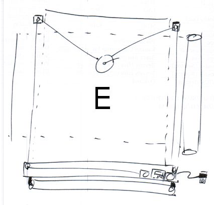
    • Design E.  As I was typing this up another idea occurred to me.
      • One of the problems I had with a box-mounted system was that getting power or a USB cable into the box was difficult.  For any interesting sized drawing the box would have to be mounted several feet off the ground.  The benefit of this design is that the paper roll could be mounted below the wooden box1 and the wooden box could be mounted near the floor – with easy access to an electrical outlet.  The downside is that the brain is basically on the floor where it can get kicked and that you’re going to have route the fishing line up over the drawing and around pulleys on either side.
      • One thing about this particular design is that I’ve drawn the DrawBot brain and both motors off to one side of the box as suggested in the “Designs, Generally” section above.

Having gone through the trouble of sketching and articulating the various benefits to each system, I think my favorite so far is Design D, with a lid over the front of the box, and the brain and motors mounted off to one side to make routing power to the project a lot easier.

Default Series Title
  1. Or, like some of the designs above, it could be mounted to the wall off to the side. []

Ideas for improving my DrawBot

Polargraph drawing by Sandy Noble

Polargraph drawing by Sandy Noble

I’ve given a lot of thought to how I can improve my DrawBot setup now that I have a Polargraph brain on the way1

  • Print a nice 3D printed plastic case for my DrawBot brain
    • The 3D printed plastic case I have for my current DrawBot doesn’t fit very well2 and doesn’t look awesome as it is literally duct taped to the plywood. An awesome new brain upgrade deserves a sweet new plastic case. I might customize Sandy’s design by adding some dual-extruded black/white hotness to it.
  • Putty, sand, prime, and paint my big chunk of plywood so it is presentable
    • Though, really, since I would just paint the wood white anyhow, I’ll most likely just prime the wood twice and call it a day.
  • Reconsider beaded cord versus fishing line
    • I’ve been using fishing line for my DrawBot, but many others including Sandy use beaded cord.
    • Fishing line. Fishing line is great when you enjoy the process of drawing as much as the drawing itself. From more than a foot or two away the pen holder looks like it is just floating in space. It is also cheap and pretty easy to manage with just a spool attached to the stepper motor. The biggest downside is that since it is wound around a spool a full turn of the spool when it is full of fishing line will let out more line than when there is little fishing line left on the spool. Every time fishing line is pulled in, it adds very slightly to the diameter of the spool and will skew the drawing. There are a few ways to compensate for this. You could enter the diameter of just the spool, spool full of fishing line, or spool half-full of fishing line. Each different usage will basically skew the drawing slightly differently. Another, more complex, alternative is to try to compensate for the extra diameter caused by the fishing line by fiddling with the code itself to consider a different spool diameter depending upon how much fishing line has been reeled in or out. Since this is way beyond my current Arduino programming capabilities, I’m just leaving it here as food for thought.
    • Beaded cord. Beaded cord is also fairly cheap, and certainly way cheaper than using a toothed belt. Since a beaded cord with matching sprocket does not accumulate on the sprocket, you have to figure out some way to manage the beaded cord – even if it just to let it hang off the side of the robot. With a kid and a cat, long loose lengths of cord might be problematic. Now that my daughter is older, this is less of a consideration. Lastly, the beaded cord will allow you to consistently draw images without having to worry about the spool-fishing line-variable diameter problem.
    • As I’ve been thinking about exhibit a drawing robot at the upcoming Bay Area Maker Faire in May
  • Design, print, and attach a mount for a large roll of paper
    • Ideally, when I’m done with a print job I can pull the paper across the print surface, tear off the finished drawing, and have a fresh new piece of paper ready to go without having to spend a lot of time re-aligning and re-mounting paper.
    • While it would be super cool to have the roll of paper motorized, I have no delusions that I’m going to do this.
  • Design, print, and use a new gondola, complete with servo powered pen-lift
    • Although I have the servo ready to connect to my existing DrawBot, I never did this. My favorite looking drawing robot drawing techniques were all TSP single line art or single-line-shading, so there was never a need for a pen lift or servo. I basically never invested the time to improve my gondola to do much more than create reliable drawings. As it is the gondola is weighed down by a piece of wire poked through a ziplock baggie with half a dozen old batteries inside. I like this solution because it is essentially re-using old batteries as small modular weights of consistent mass. But, there are so many better ways to use old batteries as weights without it being ugly. Plus, with a servo enabled gondola, I’ll be able to explore the world of vector drawings. I should probably just create a Polargraph style gondola and call it a day, since Sandy has logged more hours with a drawing robot than anyone else I’ve heard of.
  • Route wires in a pleasing manner
    • As you might have figured out by now, my current DrawBot set up is hacky and ugly. I’d like to have my DrawBot set up so that it looks nice and not a tangle of wires leaning against the wall.
Default Series Title
  1. Photo courtesy of Sandy Noble []
  2. I can only blame the designer – me []

Has it really been that long?

2012. calendarI just fired up OpenSCAD, my 3D design program of choice, and then it occurred to me that it’s been quite a while since I’ve used it.  A quick search for *.SCAD files on my hard drive revealed I haven’t updated any OpenSCAD documents since 5/13/2012. 1

That’s more than two months!  How can this be?!  I’ve got a pile of ideas stacking up.

How do you organize your ideas?  I created an e-mail address for myself “ideas@DOMAIN.com,” jot down the ideas, and send them to myself constantly.  If I have paper, I’ll sketch the idea out, take a picture, and e-mail the picture to this same address.  I think I probably send myself about two or three e-mails a day.

I can’t wait to jump back into OpenSCAD and work on some of these ideas!!!

  1. Photo courtesy of Asja Borošvia Compfight []