[2025] Google Pixel Boot Loop Fixes

In the 7 years since I wrote a blog post about rescuing my Google Pixel from a boot loop people have started reaching out to me desperately looking for a way to fix their phones.  This particularly horrible glitch happens at the worst time – when your phone storage is completely full of pictures and videos.  In my case, we were on vacation and not near wifi when I’d happened to fill up the phone storage and it got stuck in a boot loop.1

Google Support was adamant there was no way to recover my data and my options were to factory wipe the phone myself or send it to them so they could do it.  Of the resources found back in 2018, almost nothing survived Google’s march of “progress” and destruction of their own older resources.  In this case the links to Google’s own Pixel support forums and links to resources no longer work – and there are no working Archive.org / Way Back Machine links.

Anyhow, if you’re stuck in the same situation as I was – without the resources and links I had back then, perhaps if you dig around you can still find a way?

“If you have a problem, if no one else can help, and if you can find them, maybe you can…”

Before you get started – a warning.  I don’t currently have this problem and am trying to piece together how I fixed my problem 7 years ago on an older phone, using current guides that are no longer accessible.  I haven’t verified any of these links and resources, I’m just some rando on the internet who is trying to help you out because some other internet randos helped me out a long time ago.  Google has a nasty habit of deleting their own resources and shuffling things around.  I don’t know the first thing about installing new operating systems on phones and following any of these links or suggestions might permanently damage your systems.  But, as I mentioned before…  I tried this because Google Support was beyond unhelpful and I was completely out of options.

You’ve been warned

The basic framework for the fix was:

  1. Get the phone to “Recovery Mode” so at least isn’t not boot looping, overheating, and chewing up your battery.
    1. If you have an unlocked phone, or a locked phone from Google which you could theoretically unlock over a terminal, you should be able to get the phone “Safe Mode” where it will be able to turn on and access the operating system, but with limited other apps useable.
  2. Find and install the latest Android ADB (Android Debug Bridge) and FastBoot (an Android diagnostic tool)
    1. I say “latest,” but I’m not an expert and am not currently having this problem.  Perhaps it’s best to use the version which most closely matches your phone?  Anyhow, I installed ADB on the root of my PC and then created a path to it with “SET PATH=%PATH%;c:\adb” so the operating system would know it could access those resources.
  3. Try to find a “Rescue OTA” (Android Rescue Over-the-Air update) for your phone model.
    1. This would essentially be the same update that you might get when you let your phone download and install an update over night via WiFi – with the only difference that you’ve downloaded it onto your PC and are going to try to shove it back into the phone over a cable.
  4. Try to “sideload” the OTA update back into the phone using ADB / Fastboot (I don’t remember the specific steps to do this – but since these resources are constantly being worked on, I assume someone has written a guide).

If this post helped you out or you found some resources helpful, please let me know so I can update this post and help others.

Good luck!

  1. It was also overheating – which might have been a contributing factor the boot loop – or caused by the constant booting and looping []

Capstan Drives as alternatives to Planetary Gears?

Sometimes I hate the algorithm and sometimes it shows me cool new robotics / mechanics / gadgets and makersAaed Musa has been working on something called a “Capstan Drive” which is a rope driven alternative to gears.  By removing gears and  teeth and replacing them with rope you cut down on noise, eliminate backlash, high torque, low inertia, and low cost – with the major costs being low range of movement and a vertical path for the rope to travel over.  Aaed’s video is well worth a watch and blog well worth reading.  But… if you want to get a sense of how the Capstan drive works…

Capstan drive in action

The benefit of a planetary gear is that it’s a very vertically compact method for increasing rotational speed at the cost of complexity.  With a Capstan Drive (I don’t know if this is supposed to be capitalized) the rope needs to be wrapped around the thinner shaft several times to prevent slippage.  As Aaed notes:

One question that I had when first exploring this reducer was “why doesn’t the rope slip if it’s just wrapped around the smaller drum?”. The answer to that question lies in the capstan equation. With each turn of rope on a drum, the amount of friction increases exponentially. With 3-5 turns of rope, there is enough friction for slipping to not be an issue.

Aaed indicated he was using Dyneema DM20 cord as it has almost no stretch to it.  I wonder if something like fishing line would work?

DIY Lightsaber Build
  1. TwistSabers
  2. DIY Lightsaber Thoughts
  3. Wait, haven’t I worked on this before?!
  4. Considering the design elements of a DIY light saber
  5. More Musings on Lightsabers, Mechanical Components
  6. Slow Progress…
  7. Capstan Drives as alternatives to Planetary Gears?

Fixing a coiled zipper that won’t close

I have a favorite soft pencil case made from faux leather that I’ve been using for more than 20 years, but the zipper had gotten finicky and started to not close.  It started having a problem zipping closed on just one side, but today it wouldn’t close at all and the slide was just moving back and forth without closing anything at all.

After a quick search, I found a video by UCAN Zipper USA with a solution that fixed it immediately.  The narrator said the problem was the zipper started to “open a little bit” with repeated use.  I suspect the slider on my pencil case opened a little by vigorous use or sometimes by accidentally zipping it over something that had been caught in the zipper teeth.

The solution was quite simple:

  • Inspect the closing side of the zipper to see whether one side is more “open” or riding higher than the other.
  • Using pliers, gently clamp that side down just a little, then try to open/close the zipper.  If it doesn’t quite engage yet, clamp down a little more.
Gently clamp the rear / closing side of the zipper where it appears to be loose / open / ride higher

That’s it!  It worked like a charm for me.  While this worked for a coiled zipper, I suspect it would also work for a molded tooth zipper as well.

Slow Progress…

… is still progress.

I designed a planetary gear assembly, more to see whether parts this small would even turn out than to actually make a working component.  The gears are about 3 mm thick, but half of that is the larger part.  I forgot that you can’t have a two-level gear mesh against another identical gear, so these didn’t move at all.

A test planetary gear assembly

I reprinted the parts, this time increasing the center hole size and also removing the teeth off the larger side.  It kinda works, but it’s very finnicky.  This might be a side effect of these gears being very thin and the teeth very small.  I think it’s probably worth sacrificing gear ratio in favor of larger, more consistent teeth.

Small improvements

The OpenSCAD code is a mess, lots of vestigial code remains, lots of non-working parts are commented out, and it all just needs more comments in general.  I hate looking at it.  But, as one of my favorite memes goes…

I mean, he’s got a point
DIY Lightsaber Build
  1. TwistSabers
  2. DIY Lightsaber Thoughts
  3. Wait, haven’t I worked on this before?!
  4. Considering the design elements of a DIY light saber
  5. More Musings on Lightsabers, Mechanical Components
  6. Slow Progress…
  7. Capstan Drives as alternatives to Planetary Gears?

Thermal QR Code Sticker Success!

I could not be happier with how this little thermal label printer turned out!  The highest use case I had for it was to create small QR codes I could stick in my various maker notebooks so that I could easily connect specific pages in my notebooks back to blog posts, essentially being able to embed unlimited digital resources into a simple page.

This slideshow requires JavaScript.

Basically, I arranged the QR codes and text in Inkscape, exported to a flat JPG, saved to my phone, and then printed.

The failed prints you see were printed at Dense, Medium, and then Light, but all came out useless. I realized it was because I had exported the image at 72 DPI, which meant that once the image was exported to either PNG or JPG, the image had gray aliasing between what should have been sharp black and white edges.  This caused the printer to treat the grays as black, which meant the black areas were obscuring the lighter areas, making it harder to scan the images.

I exported at 900 DPI and it printed on “Light” flawlessly. Each QR code sticker is only 12.5mm square, I can fit 8 of them per sticker sheet, and each includes a short label, and can be read by my phone very easily.  Now, I don’t think a 900 DPI image is required to print fine details, but I figured why the hell not give it a shot?

The first website QR code generator I tried was actually a sneaky website.  Rather than creating a QR code for the destination, it ran the URL’s through their own URL shortener, then output that QR code.  I chose that generator since it permits you to select the desired error correction level, but the result was basically useless to me.  If I wanted a QR code pointing to a short-code, I would have pointed it at my own short URL service.  While an unshortened URL will create a larger or more dense QR code, it has the benefit of being somewhat transparent.  When you scan an unshortened URL, your scanning app can show you the destination that would be hidden by a URL shortener.  I ended up using this website to generate the QR codes which allows you to specify the URL, choose from various error correction levels, and then download in a variety of formats.

I was able to pack detailed, unshortened, URLs into just 12.5 mm square plus 4.5 point font labels.  I might be able to print smaller than this, but I don’t have any pressing need to do that.  I’ve seen some suggestions a QR code should be printed at least 10mm square, and this is just above that limit.  However, I suspect those guidelines are for commercial use, whereas these codes are likely to be rarely scanned and don’t need to be optimized for widespread use – just for my own personal benefit.

Thermal Sticker Printer
  1. QR Codes and Avatars
  2. Sticker Printer
  3. Thermal QR Code Sticker Success!

Prelude to Protractors

I was flipping through my smaller notebook and remembered I’d already posted about a credit card sized design for a protractor and ruler.  I decided to connect this to my recent other design and turn it into a short series.  This design predates the one I most recently made and shared on this site, thus the title.

While I posted a writeup to Instagram, for some reason I didn’t put anything here?!  Other websites go away over time and even if mine doesn’t last forever, well, at least it’s still mine.  Thus, here’s the photos:

This slideshow requires JavaScript.

And, just in case1 Instagram completely evaporates, here’s the writeup I posted:

A DIY protractor / ruler / template card.

I needed a quick and convenient way to make straight (ish) lines and angles that I could keep in my small notebook.

The little card is about the size of a playing card and acts like a 5mm increment ruler, 10 degree protractor, and can make it easy to draw a grid.

This all started because I was working on an electronics project, needed some resistors and haven’t memorized the color chart, decided to draw a color chart in my notebook, needed a grid / ruler, decided to design my own after seeing a neat metal one on Kickstarter.

OpenSCAD -> Inkscape -> Print -> tape to card -> craft knife -> drawing

Now I have a little template measuring tool that will let me draw circles, angles, lines, grids, and dots. I’m very happy with this. :)

I may try to lasercut one from a thin sheet of plastic

Enjoy!

Small Rulers and Protractors
  1. Inkscape Protractor and Rulers
  2. Prelude to Protractors
  1. God willing []

More Musings on Lightsabers, Mechanical Components

Other Lightsabers

After doing so many web / Youtube searches and watching so many videos on the topic of lightsabers, the algorithm quickly caught up to me and started showing me similar things.  There was one excellent video by Cleo Abram going behind the scenes at Disney to talk about how their incredible designer / engineer / imagineer Lanny Smoot invented a realistic looking lightsaber.  Another excellent video was by HeroTech going over his designs for building a DIY lightsaber with sounds, swift extension, and retraction.

This slideshow requires JavaScript.

Lightsaber Dimensions

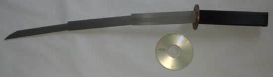
There are now so many entirely “cannon” lightsabers out there that there’s no way to know what the “real” dimensions of a lightsaber should be.  Yoda and the younglings from Revenge of the Sith likely had shorter, thinner lightsabers, Kylo Ren probably had the chonkiest, Darth Maul had the longest, etc.  I think it probably comes down to what’s the most satisfying for the user to hold.  When it comes to a DIY lightsaber where the blade is stored inside the hilt, the blade length is going to be the number of segments multiplied by the difference of the hilt length and any overlap necessary to keep the segments steady.  If we’re going with three blade segments, we can then work backwards from what would be a comfortable grip size to determine what we can fit into the hilt.

From the TwistSaber kickstarter videos, I would guesstimate the diameter of the hilt is around 2″ or 50mm.  TwistSaber core slots into their hilts, so the entire mechanism of planetary gear, screw core, and blade slides must all be thinner than the inner diameter of the hilt.

Planetary Gears

It took me an embarrassingly long time to play with the MCAD library to produce involute gears.  Once I was able to generate gears, I was banging my head against the idea of how to create properly meshing gears – that is, until Pete Wildsmith swooped in with the assist.  He pointed me in the direction of Mattias Wandel’s excellent page on the topic of meshing gears.  What I learned were these items:

  1. There is a very specific relationship to make a planetary gear where the planet gears are evenly spaced and mesh properly with both the sun and ring gears.  The number of teeth in the sun gear must be an integer multiple of the number of planet gears.  And, in turn, the number of teeth in the ring gear must be an integer multiple of the number of teeth in the sun gear.
    1. To increase the gear ratio from ring to sun gear, I needed to minimize the sun gear teeth and maximize the ring gear teeth, this meant the number of planet gears had to be minimized to keep the number of sun teeth down.  However, I liked the idea of three planet teeth basically surrounding the sun gear, keeping it aligned.  Thus, I arrived at a constant for the number of planet gears; three.  From here, the choice is whether to give the sun gear a multiple of 2 or 3 of the number of planet gears.  I chose a multiple of 3 because having only 6 teeth looked fairly weak and I didn’t like the idea of putting so much pressure on those teeth.  Thus, the sun gear has 9 teeth.  In order to get sufficient rotations of the sun gear from a half rotation of the ring gear, I chose a multiplier of 7 for the ring gear.
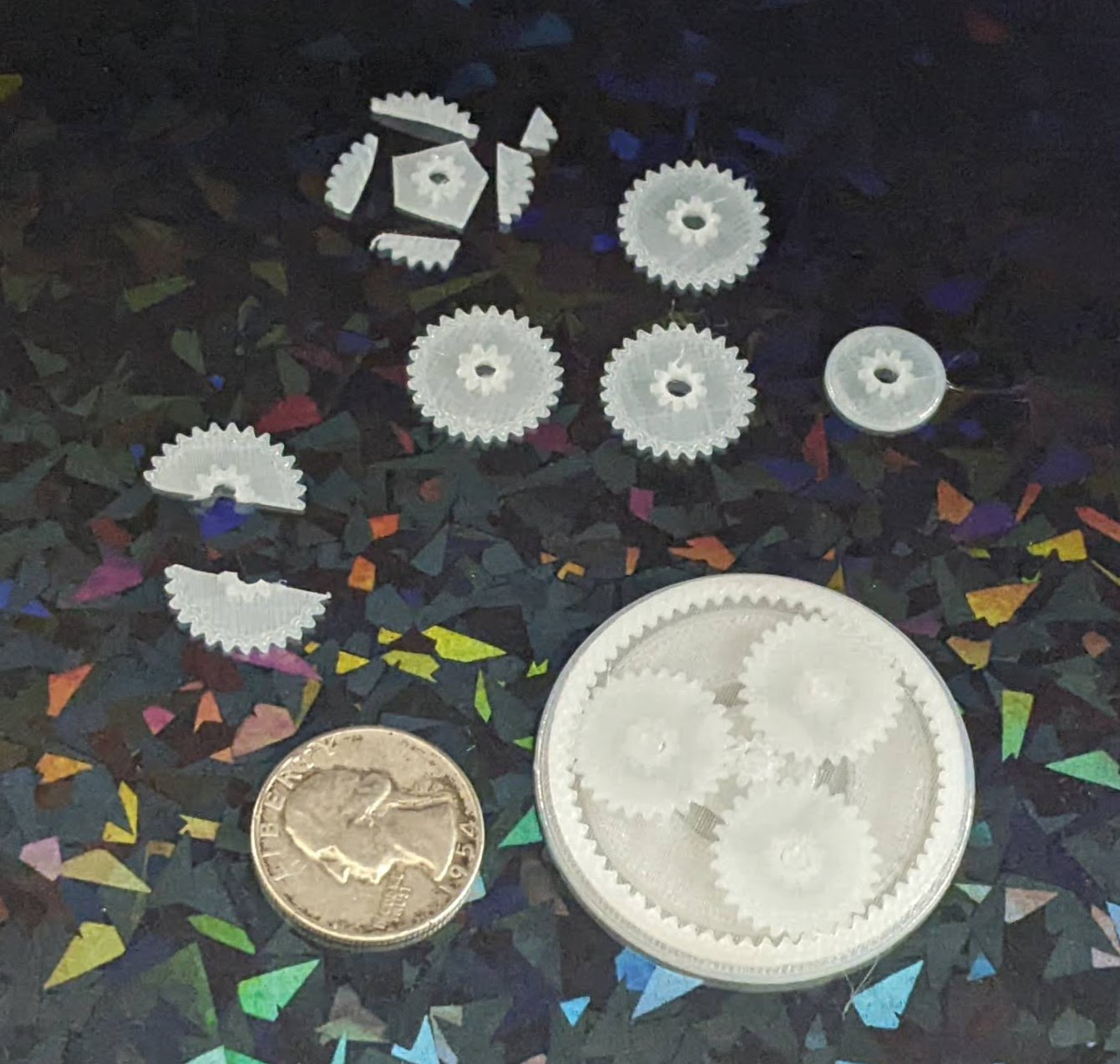
    2. Thus, we have 3 planet gears, a sun gear with 9 teeth, and ring gear with 63 teeth.
  2. The number of meshing teeth to a planet gear in the above setup is derived by subtracting the sun gear teeth from the ring gear teeth, and dividing this by two.
    1. In our instance, it would be (63 – 9)/2 = 27 teeth
  3. I learned the hard way, through trial and error, that apparently all meshing gears required the same “circular_pitch.”
    1. All this seems to do is scale the entire gear up or down in size.  Fortunately, I don’t have to understand how the library works in order to wield it’s magic.  I just fiddled with the circular pitch until the set of gears were the approximate size I needed.
  4. When orienting the gears together, I wasn’t sure how far to place the planet gear from the sun gear.  Luckily, Matthias provides this answer.  The offset of the planetary gear is calculated as (circular_pitch / π) * (Sun Teeth + Planet Teeth) / 2

Design

When I design certain mechanisms, I like to try and design the components in the smallest and most extreme ways – so the OpenSCAD designs can be modified to build something larger and less extreme.  By “most extreme ways,” I mean the design gets tested for very thin parts, very steep or low angles.  The plan is that if I could design very thin shorter parts and they appear to work, I could print them quickly to test them, iterate, and then try them at full scale.  This is why I have some half-baked cryptex designs that are absurdly small – they were designed intended to be parametric. 1

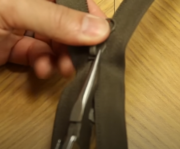
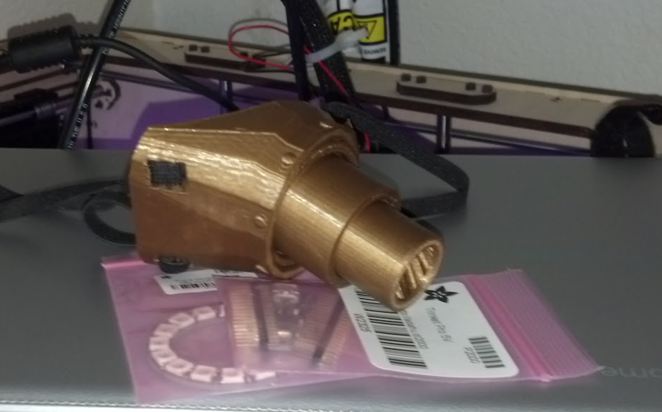
After a long and interesting search I couldn’t find the goggle components pictured in a prior post, and decided to just buckle down, tinker with some old designs on spiral telescoping parts, scale them to fit in the goggles, and start printing a new set.  Of course, as anyone knows, there is no surer way to summon a lost object than to order/manufacture a new one.  Maybe 30 minutes into the print job, I discovered the goggles printed in copper plastic sitting on a shelf.

This slideshow requires JavaScript.

It was an interesting search because I found bags of prototypes of other projects, including some thin segments of spiral telescoping parts, which gave me something to play with and be inspired by while I tinkered.

I’d like to put these designs to work building a working telescoping, planetary gear operated, set of goggles.  Who knows?  If I stuck a lens in them, perhaps a Frensel lens, they might even work as a magnifying device.  And, if not, I’ll probably try to find a way to shoehorn some LED’s into them.

One other thing that’s been eating at me.  There are essentially four blade segments.  These are the three we see throughout construction videos, plus the casing which the outermost blade segment slides along.  There are very few videos of the entire assembly working with a cutout view, but there are definitely only three actual spiral core pieces.  And, yet, when the blade is extended, we can see the tip of the blade extend out further than the outermost spiral core piece.  This means, from the hilt to the top the lightsaber is one hilt plus three blade segments long. 2  Then there’s the three central spiral cores, but if they’re fully extended and the center blade segment extends beyond the spiral core… how?

Although I haven’t seen any part of the schematics or operation to demonstrate this, I think the central blade segment might have a spiral section within it.  Unrelatedly… does this mean that all the blade and spiral segments could possibly be printed in place at the very same time?

Can LED’s be fit into an extending lightsaber?

One of my all time favorite Simpson’s clips where Skinner’s mother berates a grocery store clerk, “I want everything in one bag… and I don’t want the bag to be heavy!”

It’s certainly possible to make a realistic looking lightsaber, but it’s not likely to be sturdy enough for performance / battles.  Cleo’s video has Mr. Smoot looking mighty apprehensive that she might attempt to more than very gently gesture with the lightsaber.  You could make a lightsaber that has great sounds, great blade, great lights, but the blade won’t retract.  You could make a super dangerous plasma lightsaber capable of cutting things… with 4,000 degrees Fahrenheit, but it sure won’t be portable.

I do wonder whether it would be possible to add lights to this kind of a lightsaber.  I think it might work if there was a ring LED around the planetary gear / base of the central spiral core.  Perhaps LED’s could be placed along the inside of the blade segments, but I’m not sure how you’d route power to these things as they slid along.  Perhaps through the use of copper tape or conductive maker tape.  I think these are doable, but would require a lot of testing, calibration, and probably thicker blade segments or very thin LED’s.

DIY Lightsaber Build
  1. TwistSabers
  2. DIY Lightsaber Thoughts
  3. Wait, haven’t I worked on this before?!
  4. Considering the design elements of a DIY light saber
  5. More Musings on Lightsabers, Mechanical Components
  6. Slow Progress…
  7. Capstan Drives as alternatives to Planetary Gears?
  1. I created a working prototype, it’s about half the size of a roll of lifesavers, and then got distracted by something.  While I’d like them to be parametric, and perhaps they are, I have a feeling some odd choices in there would prevent it from being truly parametric in the way much better designer/programmers are able to accomplish []
  2. Setting aside overlap, etc []

Considering the design elements of a DIY light saber

I like to think about projects in discrete parts, trying to solve one part, then moving onto another section.  In the case of this DIY lightsaber build, I’ve been burning some brain cells thinking about this project.  Just by looking at the publicly available images of the TwistSaber, what can I infer about it’s construction?

Planetary Gears

TwistSaber Gears

I would guesstimate the gears are probably about 8 mm in height.  When I want to make a very sturdy part, I’ll use a 3 mm thickness.  However, these gears look extra chonky, so let’s go crazy.  Making further, and more in depth, guesses…  Let’s see what happens when we toss the above image into Inkscape and try to lay some star shaped polygons on it.

This slideshow requires JavaScript.

I would estimate the ring gear has 58 teeth, the planetary gears appear to have 20 teeth, and the sun gear to have 10 teeth.  When you’re dealing with printing with tight tolerances and thick (0.4 mm) extrusions, you can’t make the teeth too small, but you need enough teeth so permit smooth operation.  In any case, we can count on some sweet OpenSCAD gear library magic to help us design these planetary gears.

Screw Threads

Since we’re already talking about the planetary gears, let’s think about the spiral core rotations and screw thread.  If the 58 tooth ring gear goes through a half rotation, it will rotate the 20 tooth planetary gears by 26 teeth, causing just over 2 rotations of the 10 tooth central sun gear.  The math should math like this:

  • ((ringTeeth / planetaryTeeth)) * (0.5 rotations) * (planetaryTeeth / sunTeeth) =
  • (58 / 20) * 0.5 * (20 / 10) =
  • (58 / 20) * 0.5 * (20 / 10) =
  • 58 * 0.5  / 10 =
  • 29 / 10 = 2.9

This tells us the half turn of the hilt should cause nearly 3 turns of the central spiral core.  If we had a zero degree spiral around the central core, the screw thread would not be a spiral but rather a straight vertical line.  If we had an absolutely crazy spiral, like a million degrees of turn, the screw thread would be nearly horizontal.  We’re going to need a slope for the screw thread that causes 2.9 revolutions over 200 mm.

Screw Core

The three central screw segments have some interesting design elements.

This slideshow requires JavaScript.

By tracing the image of the screw threads, in alternating yellow and red, we can see the path of the screw threads on the camera facing side of the tube.  However, by duplicating these tracing and flipping them along a horizontal axis, we can see this means there’s just two screw threads.  In an earlier post I had wondered at the optimal number of screw threads.  You want sufficient separate threads to work to actuate the core evenly, but not so many that they introduce unnecessary friction.

We already know from various videos and GIFs the screw core is attached to the hilt at the thinnest of the three segments.  It’s interesting then that the two larger tubes have flared ends with rounded notches on one side.  Although I don’t have a photo or still frame to show this, I suspect these are meant to lock against the base of the blades.  My working theory is you insert the core into the nested blade segments, and then pull them back so they click into the base of the blades.

Here’s my thinking…  let’s assume the spiral core pieces do not connect to the blades segments at all – except at the very bottom and very top.  When you rotate the spiral core center, the other two core segments could extend – but might do so unevenly based upon how much friction there might be between any two adjacent parts.  If the spiral core pieces do connect to the blade segments, then each of the three blade segments should actuate at the same rate (rather than whichever one has the least friction).

I need to give this more thought – I have an idea, which if correct might be a simpler way to design this mechanism for 3D printing.  (It would be probably impossible for injection molding though…

Blade Segments

The blade segments are interesting in their own right.  There’s no clear picture of how many rails exist within these blade parts.  However, we might be able to extrapolate this from the portions we can see.  In the second of these two screen shots, you can see two and a half sets of rail alignment nubs.  If there is an equal number on the reverse, then perhaps there are five alignment rails inside each blade?

This slideshow requires JavaScript.

One nice thing about OpenSCAD is the use of parameters.  There’s no reason I couldn’t design a similar device, but specify the blade segments should only be 20 mm tall, and then print out an incredibly stubby light saber.  If the mechanism work, then I could just adjust the blade segment height from 20 mm to 250 mm and try printing it again.

DIY Lightsaber Build
  1. TwistSabers
  2. DIY Lightsaber Thoughts
  3. Wait, haven’t I worked on this before?!
  4. Considering the design elements of a DIY light saber
  5. More Musings on Lightsabers, Mechanical Components
  6. Slow Progress…
  7. Capstan Drives as alternatives to Planetary Gears?

Wait, haven’t I worked on this before?!

Years ago one of my kids had a pirate themed birthday party.  I interpreted it as a “space cowboy pirate” and went with a slightly Firefly-meets-Treasure Planet theme.  My outfit included a 3D printed telescoping monocle / eyepatch and a katana that collapsed into the handle.  I was going to install some Neopixels in the eyepatch / monacle, but ended up just putting more LED’s into other projects.  Anyhow, here’s a slightly blurry picture from May of 2016 featuring a print of this steampunk telescoping monocle / eyepatch, a Chromebook, and my MakerBot Replicator 1 Dual extruder in the background.

Telescoping steampunk monocle eyepatch, fit for a space pirate

This lead me to trying to track down the files for the monocle which had been originally sized to house a Circuit Playground and a battery, then the telescoping components as well.

This slideshow requires JavaScript.

If you look at the bottom edge of the telescoping components, you’ll note several1 angled “teeth” which permitted the tubes to spiral against one another – and that the top interior edge of the tubes are blocked off – creating a stop.  As you can see from the image of the assembled monocle, there was enough play between each tube that they would kind of bend downwards.  This was probably due to too much space between each tube (probably by only 0.5mm) and too little overlap at the ends (there’s probably only about 2mm overlap).  I was also able to track down the katana I designed.

Collapsing katana, CD-ROM for scale

Looking back at all of these things, the collapsing blade segments of the katana, the spiral extension of the monocle, I can’t help thinking that I’ve solved most of the problems inherent in a collapsing light saber design already.

Some other thoughts after letting this project turn over in my noggin:

  • The (original) TwistSaber Kickstarter made copious mention of not just a Discord channel, but one of the Instagram videos actually discussed a place where people could discuss assembly, waitlists, the future of the project, etc.  Unfortunately, these all seem to be closed off and all the Discord invites posted no longer work.  I put in a request to join the <shudder> Facebook group, but this hasn’t been approved yet.2
  • The tolerances on these part need to be really dialed in.  I don’t know for sure, but I got the sense from the various Reddit posts that some of the parts had very thin overhangs / ledges / latches that could break easily.  I could definitely see this happening with thin plastic tubes and tight tolerances.
  • The Kickstarter from 11/16/2024 was modest, pulling in a little north of $4k.  That’s pretty good for mostly digital goods, but probably not enough to build a whole business.  Interestingly, at the launch of TwistSaber2 the creator said “Over 1,000 people now own Twistsaber version 1.”  The first Kickstarter had only 116 backers, but they must have had significantly more direct sales through their website afterwards. (Or, perhaps they just manufactured and sold or gave away a lot of those versions)
  • I’m glad the creator went all-in on the idea with TwistSaber2.  I think it’s great they are focusing on building injection molded polycarbonate blades and metal hilts. 3 The TwistSaber2 is interesting in that it has a ~28.5″ blade design (723.9 mm) which is right in between the first TwistSaber 1 length of ~23.5″ (597 mm) and the first TwistSaber 2 length of ~30.9″ (785 mm).  My guess is this new length is probably a decent compromise between production and tooling costs as well as stability when extended.
  • I had theorized in a prior post the holes in the base of the TwistSaber core was likely to permit air flow in and out of the blade section, to prevent too much suction or pressure from impeding the function.  My guess was that if you did not include these holes, you would be creating something of a vacuum within the extending blade chamber due to the tight tolerances between the blade sections, which would prevent extension.  Then, once extended, if you tried to collapse the blade you would be fighting the compression of the air inside.  One of the videos I saw4 referred to these same features as “speed holes.”  I note the base of each of the blade sections is flat, with a hole through the center for the spiraling core, and holes in that flat section.  I’m guessing these are necessary to permit airflow throughout the blade.
  • I really like the new system of a more interesting looking blade core.  It has this cool khyber crystal looking cutout through which you can see the blade sticker which shows the blade color, some faint tracing patterns along the edge, and an interesting new and easier assembly system.

    TwistSaber 2 core assembled into hilt
  • The new assembly procedure seems to be sliding the top half of the hilt onto the blade core, followed by the bottom half which is then secured in place with a screw or bolt.  This probably makes more sense than using a twist mechanism just at the very base of the toy.
  • Obviously for maximum central core rotation and speed, it would be best to maximize the gear differentials between the ring gear to the planetary gear to the sun gear.  However, in order to not shear the sun gear off the central core, it is likely advisable to have it a minimum diameter for strength.  Thus, perhaps “maximum” rotation isn’t necessary – just a lot of rotation.
  • The nice thing about designing with OpenSCAD is that I could reuse much of the knowledge I built into my monocle designs above and even just steal some of my own design code.  A twisty core at the center, probably using an OpenSCAD screw thread library, sliding blade outside, planetary gears ideally using double helical gears to increase contact and reduce backlash.

In case anyone is wondering, I have no intention on commercializing these ideas.  I just like thinking about neat designs, making cool stuff, I want a cool light saber, and I would rather spend a ridiculous amount of time 3D printing my own than buying a pre-built / mostly pre-built one.  Patented or patent pending doesn’t prevent someone from reviewing a patent or reverse engineering an object or even building one or a thousand of something – it just prevents them from profiting from doing so.  Since the STL’s for the TwistSaber aren’t likely to be available ever again or any time soon, well, I guess buying the STL’s isn’t an option so…

I'm going to have to science the shit out of this
I’m going to have to science the shit out of this

I’m not quite prepared to really dive into the particulars on the thread sizes, since I don’t have a great sense of the more important design aspects.  I suspect the core has an outer diameter of 37.0 mm and an interior diameter of 34.6 mm.  I would probably place between 3 to 7 ridges for the the blade and screws to slide.  Assuming an outer diameter of 37.0 mm, the circumference of the blade core would be ~116.18 mm.  However, we want to fully articulate the blade using only half a turn, so let’s say ~58.09 mm.  Now, we know we want the 250 mm blade to move all the way out – but reserve 50 mm for overlap.  Thus, each segment only needs to move 200 mm.  Each of the blade sections should probably advance at the same speed, so they probably need the same screw pitch.  The three blade segments are probably 1.2 mm thick (At least, that’s about what I would choose.  I like to use wall thickness of multiples of the nozzle diameter to maximize plastic in a minimum space.  With a nozzle diameter of 0.4 mm would give us three walls or a thickness of 1.2 mm.  Each blade will probably require 0.3 – 0.5 mm space around all moving parts for each movement.  While I feel 0.3 mm is a realistic clearance on all sides for a good printer, let’s use 0.5 for ease of calculation.  If the internal diameter of the core is 34.6 mm, the central blade section would be (1.2 mm + 0.5 mm clearance) * (2 sides) * (3 blade sections) = 10.2 mm smaller than the diameter of the largest blade piece 34.6.

If we sketch out a triangle…

OpenSCAD triangle

This triangle, wrapped around the interior of the core, should describe the approximate path of the screw thread.  This is all just guesswork, but I feel it would be a good starting point to come up with some designs and test models.

DIY Lightsaber Build
  1. TwistSabers
  2. DIY Lightsaber Thoughts
  3. Wait, haven’t I worked on this before?!
  4. Considering the design elements of a DIY light saber
  5. More Musings on Lightsabers, Mechanical Components
  6. Slow Progress…
  7. Capstan Drives as alternatives to Planetary Gears?
  1. Six total []
  2. I just don’t get why so many people trust Facebook groups to act as a community or knowledge base.  I feel like this was a lesson-learned from  the Google Groups shutdown, Myspace shutdown.  If you don’t own your community location, like a wiki or a forum, there could be a rug pull at any point. []
  3. But, even so … damn if I just don’t want to build my own, you know? []
  4. I watched all of them on YouTube, Instagram, and Tiktok []

Sticker Printer

I recently purchased a small thermal label / sticker printer after seeing what amazing things @Alpenglow was doing at Teardown 2025.  I quickly picked picked one up and posted a few notes.  The bluetooth connection was a little finicky, but Android app worked well enough.  I was able to print over USB without a lot of fuss, which was great.  I was surprised that I could do so much image manipulation within the app itself.

First few test prints

I was shocked at the speed and quality of these little prints.  One of the reasons I wanted to get this little sticker printer was to add QR codes to my notebooks.  I had experimented with using my laser printer to print on packing tape, masking tape, and scotch tape.  I probably have the pictures to match these experiments somewhere, but the methodology was print some rectangles for text on a sheet of printer paper, layer packing tape over those sections, put pieces of packing, masking, and scotch tape over the areas where I was going to print.  The packing tape became a melted mess, the masking tape held the design – but smudged quickly and easily, and surprisingly the design on the scotch tape held up.  Still it was a pretty big hassle and could easily gum up my sturdy Brother printed with melted plastic.

Where was I?  A sticker printer!!!  Okay, when I am working on a project, whether that’s fleshing it out on scratch paper, putting it in a notebook, or putting together a big blog post, I sometimes wish the transition between an analog page and a digital resource (image, download, link, etc) was a lot easier.

The sticker printer I purchased came with stickers that are about 1.5″ tall by 2.75″ wide.  I think this would be enough for me to create multiple QR codes with pre-defined links to be printed at once, then store them on a sheet tucked into a notebook flap.  When I need to “embed” a link, peel the sticker, apply to page, then update my YOURLS installation so the short URL points where I need it to go.  Here’s a mockup:

Sketch idea for multiple small QR codes on stickers for a “smart” notebook

I’ll play with the idea more tomorrow…

Thermal Sticker Printer
  1. QR Codes and Avatars
  2. Sticker Printer
  3. Thermal QR Code Sticker Success!