
Doesn’t look like much, does it?
I admit it, I’m prone to verbosity. I wrote 2200 words just discussing the kinds of pen holders other people have used and another 2300 words talking about what I consider to be ideal qualities in a pen holder.1 In some ways, the pen holder is possibly the least important part of the entire robot. When you can use something like a binder clip or cardboard, hot glue, and dead batteries to create really amazing drawings, it’s almost a waste to spend any time thinking about what makes an idea way to hold a pen. However, since I’ve got the rest of the robot looking and working just like I always wanted, I’ve latched onto this last part as something I would like to optimize.
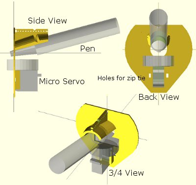
Above is an OpenSCAD rendering of a pen holder I’m getting ready to try out. As I type these words, my Replicator is a little over 50% done printing the pen holder. Before my three most recent posts discussing pen holders I had been working on an overly complicated, multi-part, pen holder. It consisted of several pieces that would be printed simultaneously, several spots for captive nuts – the features went on and on. Don’t get me wrong – a pen holder like that might be genuinely great – but I’m not sure that level of complexity is necessary or in any way worth the design time.
The design pictured above meets several of my criteria for an ideal pen holder. For your consideration, I submit the following features, design choices, and design elements:
- Just one very lightweight part. This printed part would require only a rubber band to keep the pen in place and, if you’re using a micro servo, a single zip tie to keep that in place. At the moment the design doesn’t include a space for weights. Once the part is done printing, I’m going to put it together with the micro servo and pen and see how it hangs. If it looks okay, I’ll hot glue some batteries to it in various spots. If that works well, I’ve already got a variation on this design which includes some printed tabs for adding dead batteries for weight. The part itself uses very little plastic and prints fairly quickly.
- “Full contact” stabilizer. In a prior post I discussed the several types of pen holders and how they can have a single point of contact with the drawing surface, three points of contact, or “full contact.” While the Polargraph style pen holders use a blank CD (120mm in diameter), the above just uses a mostly round shape 80mm across. I don’t know if this is wide enough or not, but this is a first draft.
- Pen held at angle. Felt pens and markers don’t really require they be held at an angle, but I can’t imagine it would hurt. Well, I suppose they could have too much ink come through – but I could just run the robot a little faster. There’s no science behind my choice of the pen tilt at a 15 degree angle, it just seemed like a reasonable number. Since it’s a parameter in the OpenSCAD file, I can easily go back and change it if this is just a terrible choice.
- Cord attachment points #3, the “Single cord convergence point, not at the pen tip.” This pen holder is designed to allow the cords to essentially meet at one specific point – namely one of the tiny holes in a row along the top edge of the pen holder. These are most visible in the top left of the above picture.
- Centering point viewer. Since the cord convergence point is centered on one of those tiny holes, the user of this pen holder can look through a tiny hole the the flat surface of the pen holder to make sure the pen holder is properly centered and homed.
- Multiple points of cord attachment. Depending upon pen type, pen weight, and pen holder weight and distribution I could imagine there might be different optimal points of cord attachment. The top edge of the pen holder has a series of holes through which the cord could be fed. The way to attach the cords would be to create a small loop in the end of the cord, feed it through one of the holes and then hook it onto the protuberance at the end of the row of holes. (You might have to look at the top left picture a bit to notice this bit). The other cord would be fed through the same hole – just on the other side and hook onto the same protuberance. This setup was inspired by Dan Royer’s multiple point of attachment set up and the AS220 labs “clip stabilizer.”
- Pen held securely in place and depth. A rubber band should do the job of keeping the pen in place nicely. I added a groove to the top edge of the holder where the rubber band can rest. I can’t imagine needing a cord attachment point as far back as the groove near the pen holding cylinder, so I fully expect the last four or five holes can be eliminated, which means I can use the groove around the pen holding cylinder as it was originally designed – to serve as the resting point for the rubber band.
- Multiple pen diameters/pen lengths. Although this holder was designed for a pen with a maximum radius of 20mm, it could probably accommodate up to 25-30mm. All but one of the pens in my house would fall in the sub-20mm-diameter category. The reason for having the rubber band point so far back along the pen is that most pens are tapered towards the marker tip, which means you can’t really hold the pen any closer than 20-30mm back from the tip. The holder is designed to hold the pen 30mm back from the pen tip, which is enough to accommodate all but the absolute largest marker.
- Holder for micro servo. The holder was specifically designed for my micro servo. Once the micro servo is inserted (in the orientation shown by the shadowy looking micro servo in the images above) one of the tabs for the micro servo sits completely flush with the flat side of the pen holder. There are holes on either side of the micro servo through which a zip tie can be fed. There’s even just enough clearance so that the zip tie itself doesn’t protrude past the flat surface of the pen holder.
- Clearance for the widest servo arm. I know many others have designed much better mechanisms for having a micro servo perform a drawing robot pen lift. Since this is literally my very first attempt to incorporate a micro servo into one of my drawing robot projects, I figured I would just use a bare-bones approach and have the servo’s arm directly push the pen holder off the drawing surface. I’m positive there are more optimal ways to do this but again, this is a first draft.
I’ve uploaded the files to Thingiverse, to be followed by my janky OpenSCAD file. It started off totally parametric and then as I got close to finishing it, I just started entering in numbers that would make it work. I’ll go back and improve it, but for now I’ll share what I’ve got.
Default Series Title- I haven’t even started blathering on about different kinds of pens! [↩]