Ideas for DrawBot Designs
I’ve been kicking around some design ideas for how my new DrawBot will look. I’d like it to be aesthetically pleasing and reasonably compact so that when not in use it will be reasonably unobtrusive. For the most part none of these designs would require the DrawBot to operate in a mechanically different way. However, most of them would probably look best with a fishing line spool rather than beaded cord and sprocket system.
- Design and create a nifty DrawBot mounting system
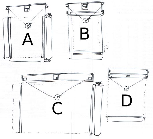
- Above you can see some of my ideas for mounting a DrawBot to a wall. It is probably most ideal for a DrawBot to operate at a slight slope – so that a little bit of gravity is keeping the drawing gondola pressed against the drawing surface. That said, here’s my thought behind some of those designs.
- Designs, Generally. Several of the designs above contemplate the drawing robot brain being housed inside a long thin box. I had tried housing my current DrawBot inside a box, but it just didn’t work very well. Since wiring would be easier if the motors are mounted near the robot brain and running the power cord to the robot would be easier if the brain were situated to one side, it might be most pleasing to use a wooden box that has a lid which can be flipped down over the front, rather than leaving the robot brain and motors exposed. One other interesting item is that while I’ve typically mounted the motors so that the motor shaft is pointed towards the wall with the spool on the outside, there’s no reason to design a clever mount which would orient the motor shaft perpendicular to the printing surface with the spool on the inside. This could result in keeping the fishing line a lot closer to the wall than would otherwise be possible.
- Design A. This design features the motors, DrawBot brain, and roll of paper mounted directly to a piece of plywood essentially as my current set up exists. I figure I could pick up some cheap hardware store rulers and nail them to the board on the left and right side to keep the paper pressed against the DrawBot surface. While this is probably the easiest design to implement, it lacks the symmetry of the other designs.
- Design B. This design features a similar motor and brain mount to Design A, except that the paper roll is mounted behind the board. This design also features a wide horizontal slot cut into the board near the top through which the paper roll could be fed. This would require the plywood board to be set off from the wall, which is not really that big a deal. One additional problem is that the best roll of paper I could find is actually a fair bit wider than the board itself. Of course, I could have someone chop down the roll of paper, but this seems like it would be a huge hassle.
- Design C. This is wall-mounted system similar to something I first tried when I set up my DrawBot. I mounted the brain and the motors inside a long thin pine box I had lying around. I had tried a number of variations on this without much success.
- Fishing line. I tried running the fishing line through holes in the bottom of the pine box, but the fishing line kept getting caught on the wood. I tried routing the fishing line through screw-in eyelets, but the fishing line would get caught on that too. In both instances the fishing line just wouldn’t run smoothly back and forth. If I tried this again, I would need to basically cut out the entire bottom of the box so that the fishing line would run off the motor and directly down onto the drawing surface. I think that unless I use bearings and pulleys, there’s no good way to route fishing line in a way that won’t be bothersome.
- Robot Mounting. What I particularly like about this set up is that all the important bits are completely enclosed inside a box that could be mounted nearly anywhere. If the paper roll was not mounted to the wall and just a sheet of paper was used instead, the entire robot would become very portable.
- Motor Mounting. Assuming the fishing line routing issue was just solved with bearings and pulleys, both motors could be set right very near to the robot brain in the center with a pulley on either end of the box. I’m not sure if it is is better to have all the weight in the center or somewhat distributed across the length of the box. That said, it would be a lot easier to deal with wiring if the parts were all close together.
- Drawing Surface. This is the big problem with this design. Since the drawing surface is the wall and most walls have some sort of texture, it would cause a degree of randomness and unevenness to creep into the drawing itself. In some cases this might be desirable, interesting, or part of the effect – but I think I just prefer a drawing to be smooth unless I specifically cause it to be otherwise.
- Paper Mounting. Assuming the robot was really installed on a wall, which does contradict somewhat with the desire to this design make the robot portable/modular, a paper roll could be mounted directly onto the wall, held in place by two hardware store rulers on either side. I suppose I could always put a big sheet of flat plastic behind the paper.
- Design D. This wall-mounted system is very similar to Design C, except that the paper roll is mounted to the box housing the robot and the paper runs behind the box.
- Aesthetics. I really like this design overall because it would be very compact, more “portable/modular” than Design C while still providing all of the functionality of Design C. Interestingly, it might actually be a lot better to mount the robot brain far to one side or the other. By doing so the AC adapter cord would not have to travel nearly as far to get to the brain.
- Mounting Considerations. One big difference is that while Design C could be mounted with all of the mounting hardware hidden by the box itself, Design D might require all of the mounting hardware to be very far to either side of the box or outside the box entirely. This design would also only require one hardware store ruler to be placed on the wall, below the robot, since the top part of the paper would be kept flush against the wall by the robot box itself. This, of course, assumes that the robot would be mounted to the wall – but not so close that it would keep the paper from unrolling behind the box.
One more DrawBot design
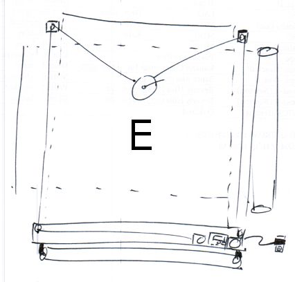
- Design E. As I was typing this up another idea occurred to me.
- One of the problems I had with a box-mounted system was that getting power or a USB cable into the box was difficult. For any interesting sized drawing the box would have to be mounted several feet off the ground. The benefit of this design is that the paper roll could be mounted below the wooden box1 and the wooden box could be mounted near the floor – with easy access to an electrical outlet. The downside is that the brain is basically on the floor where it can get kicked and that you’re going to have route the fishing line up over the drawing and around pulleys on either side.
- One thing about this particular design is that I’ve drawn the DrawBot brain and both motors off to one side of the box as suggested in the “Designs, Generally” section above.
Having gone through the trouble of sketching and articulating the various benefits to each system, I think my favorite so far is Design D, with a lid over the front of the box, and the brain and motors mounted off to one side to make routing power to the project a lot easier.
Default Series Title- Or, like some of the designs above, it could be mounted to the wall off to the side. [↩]