Overengineered Spools

Overengineered soda-fountain valves, in Hamburg, Germany

Overengineered soda-fountain valves, in Hamburg, Germany

This post is a sub-series concerning the redesign of the various parts of my DrawBot.  In short, I am looking to design/redesign

  • PolagraphSD case – discussed here – done!
  • Mounts for a paper roll – discussed here – waiting to upload…
  • Filament spools – discussed in this post – waiting to upload…
  • Stepper motor mounts – TBD1
  • Pen holder/gondola – TBD
  • Filament guides – TBD

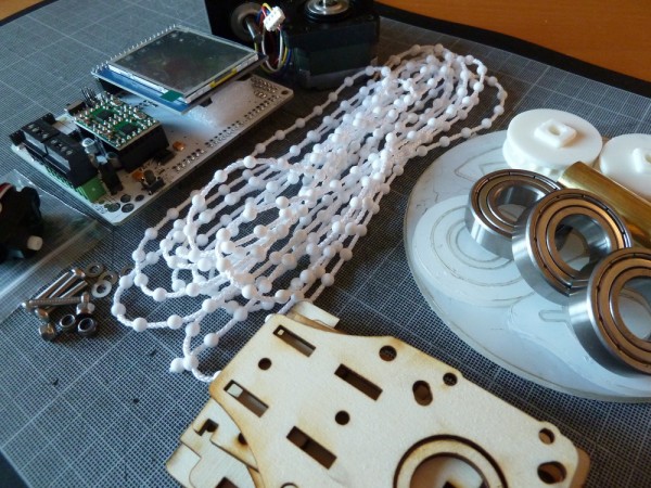
After several iterations, I printed the parts2 for spools for the newest version of my DrawBot.  ((Photo courtesy of Cory Doctorow))

The original spools I designed were simultaneously over-and-under engineered.  They were over-engineered since, for spools, they required two separate parts that would be friction-fit together around the monofilament line.  They were under-engineered since, ultimately they once came apart while still attached to the robot – resulting in a lot of monofilament line unspooling everywhere.  While not tragic, it was a small hassle.

The second iteration of the spool for my DrawBot was far simpler.  You feed the monofilament line through a tiny hole in the spool and slide it onto the stepper motor shaft.  It was a single print where one end of the spool was flat and the other end was beveled to comply with the “45 degree” rule.  This spool design worked wonderfully – once I forced them onto the stepper motor shaft.  They were also bubble gum pink, according to my daughter’s specifications.  However, once I decided to upgrade my DrawBot into a PolargraphSD, I needed to remove the motors from their mounts – which meant I needed to take the spools off.  Unfortunately, taking the spools off proved to be a problem.  I had to literally hack them off using some heavy wire cutters, pliers, and a no-foolin’ hacksaw blade.  It did not help that I printed them at 100% infill.  I cannot imagine for the life of me WHY I wanted to print spools, that are basically non-weight-bearing, in solid plastic.  The big problem with this design was that the tolerances on the spools were not right – and it is entirely possible they never would be.  Slightly too tight and they would have to be destroyed to be removed or adjusted and slightly too loose and they might not stay on the shaft or have too much play as the robot operates.  In the end, I’m just not sure I could really “trust” a single-print press-fit spool to be removable and reliable.

Which now brings me to the spools I have designed over a few days and printed yesterday.  After several revisions I now have two spools3 which are themselves compromised of two parts.  I would have to say that although this spool is more complex than the first version I used, it is probably going to be the most reliable overall.  Each spool requires 2x M3x16 bolts, 1x M3x12 bolt, and three M3 nuts.  The two M3x16 bolts hold the top and bottom parts of the spool together tightly and the single M3x12 bolt is used to tighten the spool to the motor shaft.  The result final result are two spools that are symmetrical, do not have a beveled end where monofilament can be gathered over an increasing diameter, and can be tightened on the motor shaft or removed with ease.  They’re also somewhat heavy which gives them a good respectable “this-is-definitely-a-robot-part” feeling.

I will be sharing these designs on Thingiverse and they will be able to be found under my Designs or tagged with DrawBot, but I’m going to wait until after I’ve assembled the entire robot and have actually drawn something.  For all I know these could be abysmal failures.

Stay tuned – next, I’ll overdesign motor mounts!4

Default Series Title
  1. To be designed! []
  2. Plural?!?! []
  3. Printed at only 10% infill! []
  4. Then, it’s ten somersets I’ll undertake on SOLID GROUND! []

This project is not going to overengineer itself

Seriously, why would anyone with hands buy this?

Seriously, why would anyone with hands buy this?

This weekend I worked on my DrawBot.  ((Photo courtesy of Relly Annett-Baker))  I stripped my current DrawBot for parts so that I may build it back together with a PolagraphSD brain/heart.  ((Bart?  Hain?))  Given that there aren’t a ton of parts involved, the process went quickly.  I disconnected the two steppers, pulled all the screws1 and all the nuts and bolts2 from the project.  Right now all that is left of my once mighty3 drawing robot is an Arduino and shield duct taped to a chunk of plywood.

To assemble the new robot into the desired configuration ((Sketch D for those of you playing along at home)) I needed to design:

  • A new PolargraphSD case
    • This new case is about 2/3 the volume of Sandy’s design and has vents along the sides and top to help with heat dissipation.  It can also be assembled without any tools or hardware – with the LCD actually keeping the entire thing together.  At this point I now have three perfectly serviceable cases.  My goal, once the entire robot is put together, is that it look and feel like a finished and polished project – a DONE project.  But, really, I’d like to have it semi-permanently installed somewhere in my house as a drawing appliance.  My prior ‘bot while cool with tons of nifty little hacker cred to it was little more than a chunk of plywood with bits hanging off.  I’d draw something with it, put the board away, then bring it out later.
    • My ideas for building out the robot have changed slightly since designing this case, so I might need to adjust the code and print another one.  The issue now is that the case is designed to be mounted by being bolted into the base of the project box.  However, if I do that a nut or bolt will have to stick through the back of the project which will prevent the paper roll from being able to travel behind the project box.  I figure I could print a new case and bolt it to the side of the project box – but that might interfere with the location of the motors/motor mounts.  I might be able to just ziptie the case to the top of the project box – which might not be good as the bot is expect to shake a little in operation and I don’t want the board shaken unnecessarily.  Frankly, at this point, I think I’ll get everything else situated completely within the project box and come back to figuring out how to mount the case.
    • Although, an idea which just occurred to me is that I could glue some plastic mounts, with captive nuts, into the inside of the project box and bolt the case into that.  Again, this would best be done once all the other issues are resolved.
  • New monofilament spools
    • I had to completely destroy my existing spools to get them off the motor shafts.  For some god-awful reason I printed the two spools at 100% infill creating the sturdiest monofilament spools in existence.  I cannot imagine what possessed me to do this.  They were heavy and impossible to remove cleanly from the motor shafts.  I didn’t get the tolerances right with the prior spools, so I had to force them onto the shafts – but then they were stuck.  I had to use a big pair of wirecutters to chop chunks of plastic off until I could pull the last bits free from the motor.  When I finish designing and printing a new set of spools, I’m going to make sure the tolerances are right before I assemble.  I want the spools to fit snugly becuase I don’t want the motor to slip when it reverses directions – as it will do frequently across a large drawing.
    • I’m still kicking around ideas on how to improve the spools.  My first spools were way too complex and the friction fit wasn’t enough to keep them together.  My second set was too tight and too short.  While I wouldn’t mind a friction fit spool, I need a spool that can’t come apart during operation4 , can be tightened on the motor shaft, and can be removed easily if necessary.  Additionally, I’d like the final spool to be taller – so that there is more of the spool center and less of the flared end of the spool for the filament to wind onto.  The flared end was flared so that the spool could be printed as a single piece.  While this was nice for simplicity’s sake, I found that sometimes the filament line would “ride up” the flared end – which introduces unnecessary error into the process.
    • Looking at the AS220 Labs website page for their drawing robot kit through Archive.org, you will notice that they use a tall spool with a low-friction monofilament line guide.  The benefit of the tall spool is that it can keep a more consistent diameter for more of the filament versus a narrow spool that will accumulate layers of filament more quickly.  The benefit of the line guide is that it forces the robot to maintain the proper distance between the two motors even when the spools are mounted horizontally.  I also happen to like the horizontal spool mount system since it means the motors won’t stick out from the wall quite so much.5
  • A new gondola
  • A way to mount a roll of paper to my project box
    • Besides tearing my drawing robot apart, this is the one thing I did manage to design, print, and put together over the weekend.  Since the paper roll I’m using did not come with a center of cardboard or wood or on any kind of spindle, it is not an immediately mountable thing.  My roll of paper is just that – a really long roll of paper.
    • What I wanted was a modular way to mount a roll of paper to the top of my project box so that it could be adjusted to fit different diameters and widths of paper rolls.  My solution was to print two “caps” to go at either end of the paper roll, with a hole through them to run a long wooden dowel.  The nifty part is where I then bolted two printed plastic tracks to the top of my project box, onto which I can slide a plastic arm which the wooden dowel fits into.  Once the two plastic arms are in place, they can be tightened down onto the plastic track.  The result is a rock solid paper roll mount that lets the paper roll freely turn.  I was so happy with the way this turned out I almost couldn’t see straight.  Yes, it is just a mount for a roll of paper – but it is the most solid and polished way one might hope to mount a core-less roll of paper on top of a wooden box.
  • A new way to mount the stepper motors to the project box
    • Given the amount of time I’ve spent just mounting a roll of paper and obsessing about spools, is it any wonder I haven’t finished thinking about how to mount the steppers?  With the first incarnation of my drawing robot I had designed and printed no less than three completely different motor mounts.
    • I would like the final version of the motor mounts to be easily adjustable, probably using a similar track/mount system that I used to mount the paper roll.  While this kind of solution takes more time to design, the result is a robot that can be quickly and easily improved and adjusted.  As suggested above in the spool section, I am leaning towards mounting the motors so that the shafts are horizontal on the plate of the wall.  This will let the motors keep a slim profile in the project box and allow the use of a tall spool which will enable more even and uniform reeling and unreeling of monofilament.
    • I’m tempted to incorporate a monofilament line guide directly into the motor mount.  In the interests of modularity, it makes sense to keep these things separate, but it might just make sense to do this given the limited space I’ve got within the depth of this shallow project box.6

I’m undecided whether I want to put a cover on the front of my project box.  On the one hand leaving the front of the project box open allows the viewer to peer into the robot and marvel at its simplicity.  On the other hand, without viewing the internals all you would see is a box mounted on the wall, a paper roll on top of that, a power cord coming out of the side, and a drawing pen moving by two almost imperceptible monofilament lines.  Perhaps I should explore this idea in another long winded post?

Default Series Title
  1. Four total []
  2. 12 nuts and four bolts []
  3. Mighty UGLY, that is! []
  4. When one of the friction fit spools failed mid-drawing, it was like watching my robot puke monofilament line.  Frankly, a monofilament puking robot is pretty awesome – just not when it is made from a drawing robot []
  5. If you were betting on me not being able to type an ENTIRE Page of text just on the considerations of the spools in my robot, you would have lost. []
  6. For reference, the box I’m using is less than 2 inches deep. []

Every Body Needs a Skull

Delicious brains

Delicious brains

Is there anyone out there who built their own Polargraph, but does not have a plastic case for it?1

In designing my own I’ve got two perfectly serviceable cases that I’m not going to use.

Each case fits Sandy Noble’s PolargraphSD which consists of an Arduino Mega 256 clone plus an LCD touch screen and his custom shield for running the drawing robot.  I’m also going to be taking my current Arduino Uno plus Adafruit Motor Shield powered drawing robot apart.  When I do I will have another plastic case.

If interested, please drop me a line.

Oh, what’s with the skull and brains?  Well, if you have a robotic brain, wouldn’t a nifty plastic skull go nicely with it?

Default Series Title
  1. Photo courtesy of chotda []

The Eagle Has Landed

I'M HERE!

I’M HERE!

According to the USPS my Polargraph has landed at my local post office where I keep a post office box.  ((Photo courtesy of Grant MacDonald))  Hopefully I can pick it up after work today!

How exciting!  I can’t wait to pull my existing DrawBot apart and reassemble the bits with a Polargraph brain.

Default Series Title

DrawBot Aesthetic Re-Design Ideas

Ideas for DrawBot Designs

Ideas for DrawBot Designs

I’ve been kicking around some design ideas for how my new DrawBot will look.  I’d like it to be aesthetically pleasing and reasonably compact so that when not in use it will be reasonably unobtrusive.  For the most part none of these designs would require the DrawBot to operate in a mechanically different way.  However, most of them would probably look best with a fishing line spool rather than beaded cord and sprocket system.

  • Design and create a nifty DrawBot mounting system
    • Above you can see some of my ideas for mounting a DrawBot to a wall. It is probably most ideal for a DrawBot to operate at a slight slope – so that a little bit of gravity is keeping the drawing gondola pressed against the drawing surface. That said, here’s my thought behind some of those designs.
    • Designs, Generally.  Several of the designs above contemplate the drawing robot brain being housed inside a long thin box.  I had tried housing my current DrawBot inside a box, but it just didn’t work very well.  Since wiring would be easier if the motors are mounted near the robot brain and running the power cord to the robot would be easier if the brain were situated to one side, it might be most pleasing to use a wooden box that has a lid which can be flipped down over the front, rather than leaving the robot brain and motors exposed.  One other interesting item is that while I’ve typically mounted the motors so that the motor shaft is pointed towards the wall with the spool on the outside, there’s no reason to design a clever mount which would orient the motor shaft perpendicular to the printing surface with the spool on the inside.  This could result in keeping the fishing line a lot closer to the wall than would otherwise be possible.
    • Design A. This design features the motors, DrawBot brain, and roll of paper mounted directly to a piece of plywood essentially as my current set up exists. I figure I could pick up some cheap hardware store rulers and nail them to the board on the left and right side to keep the paper pressed against the DrawBot surface. While this is probably the easiest design to implement, it lacks the symmetry of the other designs.
    • Design B. This design features a similar motor and brain mount to Design A, except that the paper roll is mounted behind the board. This design also features a wide horizontal slot cut into the board near the top through which the paper roll could be fed. This would require the plywood board to be set off from the wall, which is not really that big a deal. One additional problem is that the best roll of paper I could find is actually a fair bit wider than the board itself. Of course, I could have someone chop down the roll of paper, but this seems like it would be a huge hassle.
    • Design C. This is wall-mounted system similar to something I first tried when I set up my DrawBot. I mounted the brain and the motors inside a long thin pine box I had lying around. I had tried a number of variations on this without much success.
      • Fishing line. I tried running the fishing line through holes in the bottom of the pine box, but the fishing line kept getting caught on the wood. I tried routing the fishing line through screw-in eyelets, but the fishing line would get caught on that too. In both instances the fishing line just wouldn’t run smoothly back and forth. If I tried this again, I would need to basically cut out the entire bottom of the box so that the fishing line would run off the motor and directly down onto the drawing surface. I think that unless I use bearings and pulleys, there’s no good way to route fishing line in a way that won’t be bothersome.
      • Robot Mounting. What I particularly like about this set up is that all the important bits are completely enclosed inside a box that could be mounted nearly anywhere. If the paper roll was not mounted to the wall and just a sheet of paper was used instead, the entire robot would become very portable.
      • Motor Mounting. Assuming the fishing line routing issue was just solved with bearings and pulleys, both motors could be set right very near to the robot brain in the center with a pulley on either end of the box. I’m not sure if it is is better to have all the weight in the center or somewhat distributed across the length of the box. That said, it would be a lot easier to deal with wiring if the parts were all close together.
      • Drawing Surface. This is the big problem with this design. Since the drawing surface is the wall and most walls have some sort of texture, it would cause a degree of randomness and unevenness to creep into the drawing itself. In some cases this might be desirable, interesting, or part of the effect – but I think I just prefer a drawing to be smooth unless I specifically cause it to be otherwise.
      • Paper Mounting. Assuming the robot was really installed on a wall, which does contradict somewhat with the desire to this design make the robot portable/modular, a paper roll could be mounted directly onto the wall, held in place by two hardware store rulers on either side. I suppose I could always put a big sheet of flat plastic behind the paper.
    • Design D. This wall-mounted system is very similar to Design C, except that the paper roll is mounted to the box housing the robot and the paper runs behind the box.
      • Aesthetics. I really like this design overall because it would be very compact, more “portable/modular” than Design C while still providing all of the functionality of Design C. Interestingly, it might actually be a lot better to mount the robot brain far to one side or the other. By doing so the AC adapter cord would not have to travel nearly as far to get to the brain.
      • Mounting Considerations. One big difference is that while Design C could be mounted with all of the mounting hardware hidden by the box itself, Design D might require all of the mounting hardware to be very far to either side of the box or outside the box entirely. This design would also only require one hardware store ruler to be placed on the wall, below the robot, since the top part of the paper would be kept flush against the wall by the robot box itself. This, of course, assumes that the robot would be mounted to the wall – but not so close that it would keep the paper from unrolling behind the box.

        One more DrawBot design

        One more DrawBot design

    • Design E.  As I was typing this up another idea occurred to me.
      • One of the problems I had with a box-mounted system was that getting power or a USB cable into the box was difficult.  For any interesting sized drawing the box would have to be mounted several feet off the ground.  The benefit of this design is that the paper roll could be mounted below the wooden box1 and the wooden box could be mounted near the floor – with easy access to an electrical outlet.  The downside is that the brain is basically on the floor where it can get kicked and that you’re going to have route the fishing line up over the drawing and around pulleys on either side.
      • One thing about this particular design is that I’ve drawn the DrawBot brain and both motors off to one side of the box as suggested in the “Designs, Generally” section above.

Having gone through the trouble of sketching and articulating the various benefits to each system, I think my favorite so far is Design D, with a lid over the front of the box, and the brain and motors mounted off to one side to make routing power to the project a lot easier.

Default Series Title
  1. Or, like some of the designs above, it could be mounted to the wall off to the side. []

Ideas for improving my DrawBot

Polargraph drawing by Sandy Noble

Polargraph drawing by Sandy Noble

I’ve given a lot of thought to how I can improve my DrawBot setup now that I have a Polargraph brain on the way1

  • Print a nice 3D printed plastic case for my DrawBot brain
    • The 3D printed plastic case I have for my current DrawBot doesn’t fit very well2 and doesn’t look awesome as it is literally duct taped to the plywood. An awesome new brain upgrade deserves a sweet new plastic case. I might customize Sandy’s design by adding some dual-extruded black/white hotness to it.
  • Putty, sand, prime, and paint my big chunk of plywood so it is presentable
    • Though, really, since I would just paint the wood white anyhow, I’ll most likely just prime the wood twice and call it a day.
  • Reconsider beaded cord versus fishing line
    • I’ve been using fishing line for my DrawBot, but many others including Sandy use beaded cord.
    • Fishing line. Fishing line is great when you enjoy the process of drawing as much as the drawing itself. From more than a foot or two away the pen holder looks like it is just floating in space. It is also cheap and pretty easy to manage with just a spool attached to the stepper motor. The biggest downside is that since it is wound around a spool a full turn of the spool when it is full of fishing line will let out more line than when there is little fishing line left on the spool. Every time fishing line is pulled in, it adds very slightly to the diameter of the spool and will skew the drawing. There are a few ways to compensate for this. You could enter the diameter of just the spool, spool full of fishing line, or spool half-full of fishing line. Each different usage will basically skew the drawing slightly differently. Another, more complex, alternative is to try to compensate for the extra diameter caused by the fishing line by fiddling with the code itself to consider a different spool diameter depending upon how much fishing line has been reeled in or out. Since this is way beyond my current Arduino programming capabilities, I’m just leaving it here as food for thought.
    • Beaded cord. Beaded cord is also fairly cheap, and certainly way cheaper than using a toothed belt. Since a beaded cord with matching sprocket does not accumulate on the sprocket, you have to figure out some way to manage the beaded cord – even if it just to let it hang off the side of the robot. With a kid and a cat, long loose lengths of cord might be problematic. Now that my daughter is older, this is less of a consideration. Lastly, the beaded cord will allow you to consistently draw images without having to worry about the spool-fishing line-variable diameter problem.
    • As I’ve been thinking about exhibit a drawing robot at the upcoming Bay Area Maker Faire in May
  • Design, print, and attach a mount for a large roll of paper
    • Ideally, when I’m done with a print job I can pull the paper across the print surface, tear off the finished drawing, and have a fresh new piece of paper ready to go without having to spend a lot of time re-aligning and re-mounting paper.
    • While it would be super cool to have the roll of paper motorized, I have no delusions that I’m going to do this.
  • Design, print, and use a new gondola, complete with servo powered pen-lift
    • Although I have the servo ready to connect to my existing DrawBot, I never did this. My favorite looking drawing robot drawing techniques were all TSP single line art or single-line-shading, so there was never a need for a pen lift or servo. I basically never invested the time to improve my gondola to do much more than create reliable drawings. As it is the gondola is weighed down by a piece of wire poked through a ziplock baggie with half a dozen old batteries inside. I like this solution because it is essentially re-using old batteries as small modular weights of consistent mass. But, there are so many better ways to use old batteries as weights without it being ugly. Plus, with a servo enabled gondola, I’ll be able to explore the world of vector drawings. I should probably just create a Polargraph style gondola and call it a day, since Sandy has logged more hours with a drawing robot than anyone else I’ve heard of.
  • Route wires in a pleasing manner
    • As you might have figured out by now, my current DrawBot set up is hacky and ugly. I’d like to have my DrawBot set up so that it looks nice and not a tangle of wires leaning against the wall.
Default Series Title
  1. Photo courtesy of Sandy Noble []
  2. I can only blame the designer – me []

All New Polargraph on the way!!!

Polargraph on the way!

Polargraph on the way!

A little while ago I purchased a Polargraph kit from Sandy Noble and now it’s on the way!!!

Sandy is responsible for having put together the best instructions for building a Polargraph/drawbot anywhere on the web.  Sandy’s latest kit uses an Arduino Mega clone, a shield specifically designed by Sandy to provide all the Polargraph functions, two StepStick motor drivers, an SD card slot, socket for an XBee wireless module, connections for endstop and servo support, and – best of all – an LCD touch screen interface.

While my own DrawBot was built entirely from off-the-shelf parts, I’d like to make it really polished.  At the moment my DrawBot does not look like much.  It is two motors bolted to a chunk of plywood with some circuit boards in a plastic holder which is duct taped to the chunk of plywood.  It works and is as reliable as the PC operating it, but it is far from pretty.  Stay tuned for some new design ideas!

Default Series Title

Maze Code + Polargraph?


My RSS feed for Slashdot brought my attention to an article on Slate.  The Slashdot summary stated:

This Slate article talks about a single line of code — 10 PRINT CHR$ (205.5 + RND (1)); : GOTO 10 — and how it manages to create a complicated maze without the use of a loop, variables and without very complicated syntax.

Even though that “one line” of code really is two lines and it really does use a loop, that short string of code is still very interesting.  While the way the code generates a maze isn’t immediately intuitive, it becomes obvious once you watch a bit of the video above.  All that code does is randomly kick out a forward slash or backward slash.  Once they wrap around to the next line, they start to form what looks like a maze.

As a little exercise I created something similar using PHP.  To make that work I had to use a fair bit of CSS to make it look decent.  In any case, it occurred to me that this would be a wonderful project for a Polargraph! Draw a random forward slash or backslash, get to the end of the line and make a bunch more on the return line.  How awesome would a huge paper roll of nothing but a giant maze look?

I think I may have found a project cool enough to show off at Maker Faire.  :)

Default Series Title

Why do DrawBots draw on walls?

A wall crawler - on the floor

A wall crawler – on the floor

A commenter named Ellison left a deceptively simple question on my first post in this DrawBot series.1

Ellison:  Why do it on a wall? Why not a drawing robot that draws on a large piece of paper on the ground? I think you’ll get better results from that.

I think there are a lot of good reasons reasons – some aesthetic, some technical, some practical – for having a DrawBot that draws on walls (or other vertical surfaces).

Aesthetically, I really like having a DrawBot that draws on vertical surfaces.  When placed in the room or an adjoining room, I can watch it scritch-scratching away at an enormous drawing.  In much the same way a snail’s meandering trail can be captivating, a DrawBot working out a TSP single-line-art drawing turns an apparently meaningless series of turns into a mass of scrawls that resolve into a work of art as soon as you take a step back. 2

Technically, the DrawBot is an exceedingly simple device.  You could build it out of little more than Arduino, a motorshield, two motors, string, a pen, and whatever you might have lying around.  Much of these pieces you could probably even scavenge for or salvage from other things.  In fact, only the Arduino and motorshield are things you wouldn’t be able to dumpster dive for.  The device works by moving the two motors in concert, such that by varying the length of string reeled in or out by a given motor is used to move the pen in an XY plane.  The one “ingredient” not listed in the preceding sentences is, of course, gravity.  If the point where the two strings meet at the pen did not hang essentially straight down, pulled constantly by gravity, the pen could go just about anywhere.  If you were to place a normally vertical standing DrawBot flat on the ground, the pen would no longer be pulled away from the two motors – and would just flop onto the drawing surface.  Now, you could add two more motors and more string and build a gondola that holds the pen vertically on a flat DrawBot surface while writing a lot more code…  However, I am doubtful you would get any more precision out of such a setup.  And, if you really require precision – an XY plotter might be more to your liking.  An XY plotter build would require lots of hardware (belts and metal rods or metal extrusions), more tools, and be big and heavy, and limited in the size of its drawing capabilities.  It would also be capable of really amazing speeds.  That’s a lot of extra materials, work, custom coding, and loss of drawing capacity for a dubious trade off in

As a matter of practicality, the simplicity of design and materials means this is an extremely cheap project.  An Arduino is only going to set you back about $30 and clones are as cheap as $15.  I picked up two of Adafruit’s motor shields on sale for $12 each, but they’re normally $20.  Screws and/or bolts, beaded cord or wire or fishing line, a big piece of wood or mounting things directly to a wall, 3D printed spools or just leftover spools from thread, a 3D printed gondola or a lasercut gondola or even a big red binder clip.3  Seriously, if you’ve got about $35 and some free time, you’re basically half way to building an awesome fun robot that can make arbitrarily large drawings.  If you’re willing to buy all the materials, it probably won’t cost you more than $150.

I’ll say it again – a Polargraph DrawBot is a quick, cheap, easy, entertaining, and useful robotics project – especially for beginners.  Outside of my 3D printers, this was easily the most rewarding DIY project I’ve ever attempted.  The results are astoundingly disproportionately awesome to the amount of time, energy, skill, and money used to achieve them.

Seriously, what are you waiting for?!  Go order a Polargraph kit from Sandy Noble45 or source the parts from Adafruit6 .7  Or, if you’re going to scavenge and/or source some parts, check out my Polargraph DrawBot parts/shopping lists.

Default Series Title
  1. Photo courtesy of The Kozy Shack []
  2. And, I wonder – if you could map all snails in the world at the same time, could they be working in concert on an enormous message?  Perhaps something along the lines of “So long, and thanks for all the fish”? []
  3. I just love that Polargraph video by Sandy Noble.  To see binder clip in action, skip ahead to 0:27. []
  4. Whose open source work I use for my own DrawBot []
  5. The next time he’s in stock, you better pull the trigger – he runs out of stock SUPER fast []
  6. Where I bought most of my parts! []
  7. And, why not tell them I sent you too? []

The biggest inkjet printer ever

Big Printer

Big Printer

The other day I wondered what people have done with their InkShields1 2  Then I got to wondering what people were doing to mount their InkShield printer heads and move them around.  Then I thought… hey!  It would be pretty awesome to attach an InkShield printer head to a Polargraph / DrawBot gondola.

I could see how an InkShield might improve a Polargraph.  You could theoretically have a small sensor to test the ink levels and pump more ink in from a larger reservoir – and never worry about a pen running out of ink again.

I could see how a Polargraph might improve an InkShield.  With a DrawBot string setup, you wouldn’t need a huge or expensive XY gantry – just a lot of string, two motors, and some other bits and bobs.

Default Series Title
  1. An InkShield is an Arduino shield that allows the Arduino to control an inkjet cartridge. []
  2. Photo courtesy of iLEZ iLEZ []